You made your model. You checked the clashes and assigned numbering. Now, you can generate your drawings. In Advance Steel, you can make drawings in two ways: the Drawing Processes method and the Drawing Styles method and browse your documentation in Document Manager.
Table Of Contents
- Document Manager
- Drawing Creation Methods
- Creating Drawings Using Drawing Processes Method
- Producing The Drawings Based On The Camera Views
- Producing The Drawings Of The Selected Single Parts
- Generate The Drawings Of The Selected Assemblies Without The Attached Parts
- Generate The Drawings Of The Selected Assemblies With The Attached Parts
Location of Detail Documents - Document Manager
Once the drawings are created (or any document) in Advance Steel, you can find them in the Document Manager. The Document Manager is the interface for managing all documents created in Advance Steel.
In the Document Manager, you have access to all the documents, such as detailed drawings, bill of materials, parts list, and NC/DStV files. You can preview all the documents, or by double-clicking them, you can open them. If any document needs to be updated, it will be placed in the Update Required category – that way, it is easily identified.
Advance Steel uses a specific procedure to create subfolders in the Project Folder where your current drawing is located. Advance Steel will create a folder with the file name of the project you are currently working on.
Here is an example of the Platform 2A RV project file name with the Platform 2A RV automatically created project folder structure:

Folders are created for each document category type. All generated drawings are saved in the Details folder.
Note: If you batch print in PDF, the PDF will be saved in the model’s main file location, with the same name as the model file name.
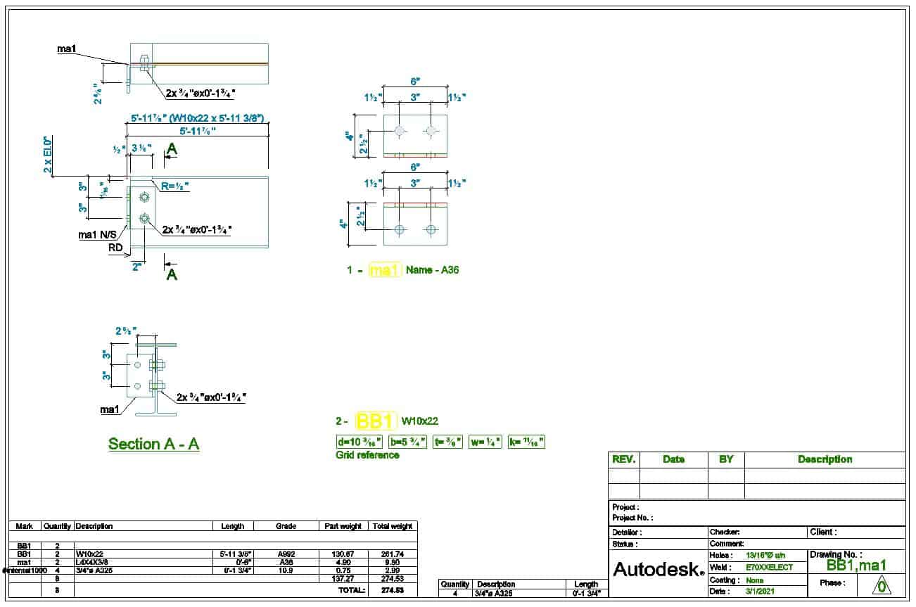
For all generated drawings, you can change their prototypes, update them with or without a revision, delete or print them in the Document Manager.
Accessing The Document Manager
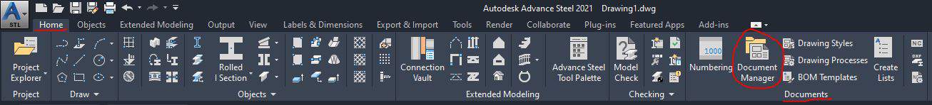
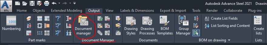
You can access the Document Manager either from the Home ribbon tab or from the Output ribbon tab:
Accessing Document Manager From Home Tab:
Home tab > Documents panel > Document Manager
Accessing Document Manager From Output Tab:
Output tab > Documents Manager panel > Document Manager
Drawing Creation Methods
Accessing The Tools
You can access both Drawing Processes and Drawing Styles from the Output ribbon tab:
Output tab > Documents panel > Drawing Processes and Drawing Styles

Drawing Processes
Drawing Processes will create automatic drawings and place them on single or multiple drawing files, using predefined steps. The predefined steps are used to specify the Prototype (Template) to be used, the scales, the view, orientation, etc.
Drawing Styles
When using the Drawing Styles method, you are required to manually specify all the steps for generation drawings. These steps include selecting objects, specifying the scale, drawing number, selecting the Prototype (Template), etc.
Creating Drawings Using Drawing Processes Method
You can produce the drawings using the following methods:
Camera
You can create Cameras in the Model key locations first and then create drawings based on those Camera Views. It is mainly used to produce (GA) General Arrangement drawings, Anchor Plan drawings, Plans, Elevations, Connection Details, etc.
You can check this post to learn everything about Cameras in Advance Steel.
Single Part
Used to detail single parts of the model. You can place the drawing views of multiple parts on a single sheet or multiple views of one single part per sheet.
Assembly
Used to detail the main parts and assemblies of your model. You can place only the assembly views on the drawing or all the associated part views.
Producing The Drawings Based On The Camera Views
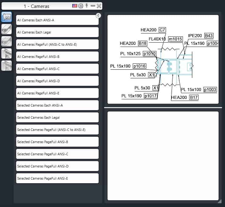
- Select the Camerasyou want to use in your drawing
- Activate the Drawing Processes Paletteand Cameras category
- Select the process you want to use from the multiple options available
Producing The Drawings Of The Selected Single Parts
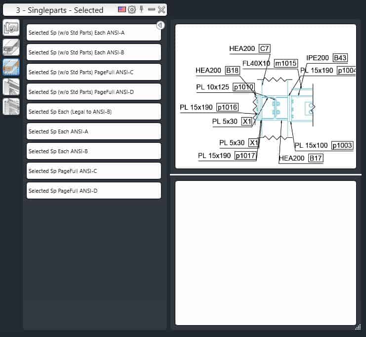
- Select the objects of your modelthat you want to use to make drawings
- In the Drawing Processes Palette,select Single Parts – Selected category
- Select the process you want to use to produce the single part drawings drawing
- The Processes Properties dialog box will open
- Close the dialog box by clicking OK
- The drawing will be created
Generate The Drawings Of The Selected Assemblies Without The Attached Parts
When making documentation of the Assemblies in your model, you can produce the drawing views of the assemblies with or without the attached parts. I recommend using the selected assemblies only.
How you can make drawings without the attached parts:
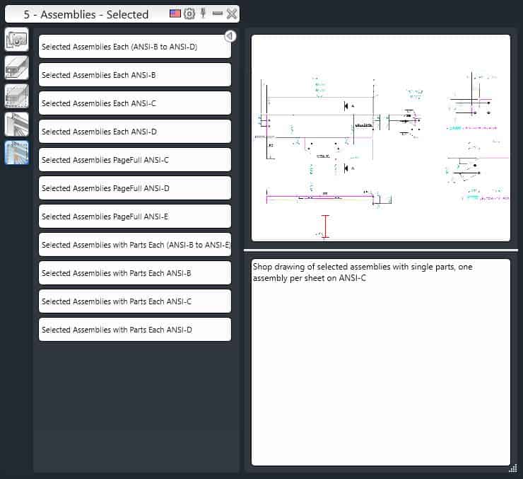
- In the Drawing Processes Palette, from the Toolbar,activate the Assemblies category; various processes will be displayed (see in the picture above)
- In your model, select the main part of the assembly whose drawing you want to produce
- In the Drawing Processes Palette, select the process of making drawings of the assembly withoutthe attached parts (upper 7 categories)
- The Process Propertiesdialog box will be displayed
- Click OK in the dialog box
- The drawing is created
Generate The Drawings Of The Selected Assemblies With The Attached Parts
Here is the procedure for creating drawings of Selected Assemblies with the Attached Parts:
- In the Drawing Processes Palette, from the Toolbar, activate the Assembliescategory; various processes will be displayed (see in the picture above)
- In your model, select the main part of the assembly whose drawing you want to produce
- In the Drawing Processes Palette, select the process of making drawings of the assembly withthe attached parts (lower 4 categories)
- The Process Propertiesdialog box will be displayed
- Click OK in the dialog box
- The drawing is created