How Buildings Are Classified (And Why It Matters to You)
Did you know that buildings are grouped into different categories based on how risky it would be if something went wrong with them? It’s true! There’s a simple system that classifies buildings from Category I to Category IV.
Category I includes things like storage sheds or barns—basically, buildings where, if they failed, no one would be in serious danger. On the other end, Category IV includes places like hospitals, fire stations, or emergency centers—critical buildings that absolutely need to stay standing and functional, especially during disasters.
Every building gets placed in the highest risk category that fits its purpose. And sometimes, a building can even fall into more than one category, depending on how it’s used and how much load it’s expected to carry.
It’s all part of making sure our structures are as safe and reliable as possible!
ASCE Table 1.1 – Risk Categories: What Type of Building Is It?
This table shows how buildings are grouped based on how important they are and how serious it would be if something went wrong. The higher the category, the more critical the building is in keeping people safe or society running smoothly.
| Risk Category | What Kind of Buildings? |
|---|---|
| Category I – Low Risk | Simple buildings like farm sheds, temporary tents, or storage units. If these structures fail, there’s little to no risk to people. |
| Category II – Standard | Most everyday buildings, like homes, offices, and small shops. These are considered normal risk structures. |
| Category III – Important to Community | Buildings that could seriously disrupt life if they failed. Examples include: – Places where over 300 people gather – Daycares with more than 150 children – Schools with more than 250 students or colleges with over 500 – Nursing homes or health care with 50+ residents – Jails or detention centers – Utilities like power stations, water treatment plants, and major communication hubs |
| Category IV – Essential Facilities | These are buildings that must stay operational in emergencies, like: – Hospitals – Police and fire stations – Ambulance services – Emergency shelters – Buildings needed for disaster response and recovery |
Building Codes: Keeping Us Safe by Design
Have you ever wondered how buildings are made safe, sturdy, and reliable? That’s where building codes come in. These are official rules that towns and cities across the U.S. follow to make sure that every building—whether it’s a house, a school, or a skyscraper—is designed and built to protect public safety and well-being.
Where Did These Codes Come From?
Before the 2000s, different parts of the country followed different rulebooks, depending on where you lived:
- The BOCA National Building Code (used in the Northeast and Midwest)
- The Uniform Building Code (popular in the West)
- The Standard Building Code (mostly in the South)
These codes were updated every few years, but having three separate systems made things confusing, especially for builders working in multiple regions.
A Unified Code for Everyone
In 1994, a group called the International Code Council (ICC) was formed to simplify things. Their goal? Combine all the regional codes into one clear, nationwide standard. The result was the International Building Code (IBC).
Now, nearly every city and state uses the IBC as their official code
The first IBC came out in 2000. It was revised in 2003, 2006, and again in 2012
Now, nearly every city and state uses the IBC as their official code
What About Structural Loads?
When it comes to how much weight, wind, snow, or even earthquake force a building must be able to handle, the IBC points to a trusted guide:
ASCE 7 – short for Minimum Design Loads for Buildings and Other Structures, published by the American Society of Civil Engineers.
This document serves as a go-to reference for engineers, enabling them to design buildings that can withstand real-world forces while keeping everyone inside safe and sound.
Understanding Tributary Area – A Friendly Guide
When working with structural loads, especially using the ASCE 7-10 standard, there’s an important concept to grasp: tributary area. Don’t worry—it sounds more intimidating than it really is! Let’s walk through it together.
The ASCE 7-10 provides standard unit loads—these are loads defined per unit area (like pounds per square foot). But structural elements like beams or girders don’t just hold one square foot—they support larger areas. So, to find the total load a beam carries, we multiply the unit load by the effective area (or tributary area) of that beam.
In some cases, the code gives us concentrated loads, which are more localized. For those, it’s essential to consider where they act to understand their maximum impact on the structure.
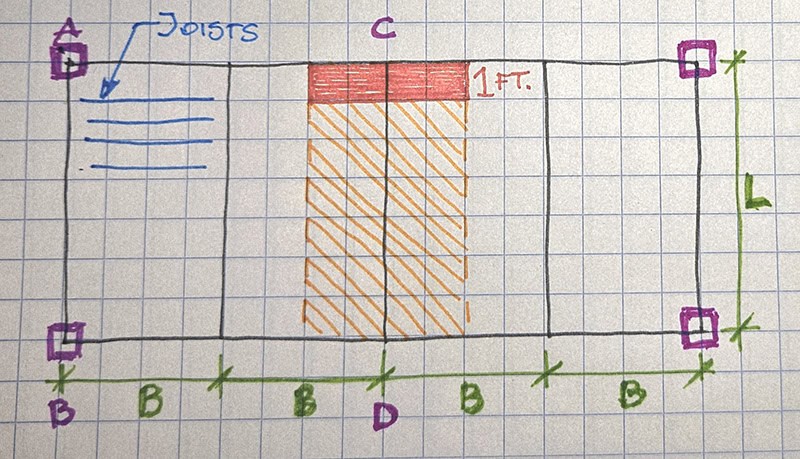
Let’s look at a simple example. In the parallel framing system (check out Figure 1.1 above), the beam labeled CD gets its load from the floor extending halfway to the next beam on either side. This gives it a tributary area of B × L (width times length). So the total load on the beam CD is:
W = w × B × L (where w is the unit load)
Now, what about an exterior beam like AB? Since there’s only load coming from one side, its tributary area is ½B × L.
Here’s a helpful tip: if you imagine a 1-foot-wide strip running across the floor, the load from that strip becomes w × B, which is the uniform load per foot along the beam. Pretty neat, right?
What About Girders?
Girders receive point loads from the beams they support—those are the reactions at beam ends. But if the beams are close together, the girder can be treated as carrying a uniform load from a tributary area, like 2B × L.
A Closer Look at Beam Loading
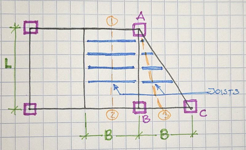
Let’s dive into Figure 1.2 (again, refer to the figure if you can!). In it:
- Beam AB supports two kinds of loads:
- A rectangular load from area A-B-2-1, which is BL/2.
- A triangular load from area A-B-3, which is ½ × BL/2.
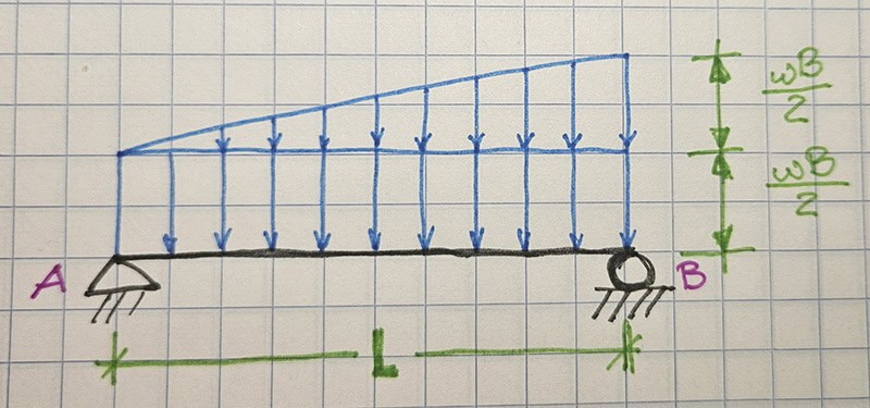
This creates a combination of uniform and triangular loading, as shown in Figure 1.3.
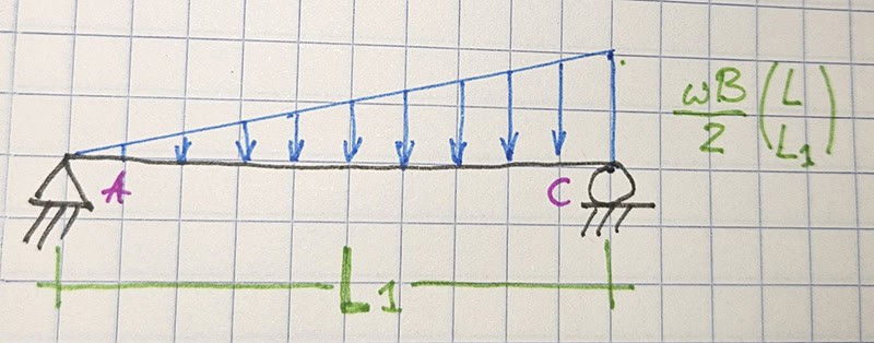
- Beam AC supports a triangular load from area A-C-3, also wBL/4. But this time, the beam is diagonal—so instead of length L, its length is L₁ = √(L² + B²). That slight geometry twist affects how we represent the load (shown in Figure 1.4).
Why Does Framing Matter?
The way you lay out your floor framing affects the tributary areas—and therefore the loading—on each element. Different arrangements (like in Figures 1.5 and 1.6) will give different load patterns. That’s why it’s important to consider your framing system early in the design.
Example 1.1 – Putting It All Together
Let’s say:
- Span L = 30 ft
- Beam spacing B = 10 ft
- Unit load on the floor w = 60 lb/ft²
Beam AB:
- Rectangular tributary area per foot = 1 × 5 = 5 ft²/ft
- Uniform load per foot = 60 × 5 = 300 lb/ft
- Triangular area total = ½ × 5 × 30 = 75 ft²
- Total triangular load = 60 × 75 = 4500 lb
- Triangular load formula = ½ × w × L = 4500 → solve for w
- Solving: w = 300 lb/ft
- The loading pattern is shown in Figure 1.7
Understanding tributary areas makes structural design more intuitive. It’s all about seeing how the structure “collects” loads and transfers them down safely. Once you get the hang of it, it’s a powerful tool in your engineering toolkit!