When you need to place a concrete beam in your Advance Steel project, the Concrete Beam tool is the right tool to use. Below you will find all the information about how to insert and modify your concrete beam, so read on.
Table of Contents

Accessing the Concrete Beam Tool
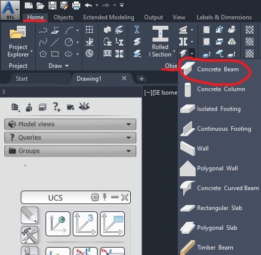
You can access the Concrete Beam tool either from the Home ribbon tab or from the Objects tab. To access from Home tab:
Home tab > Objects panel > Concrete Beam
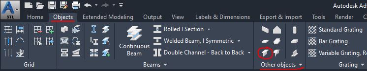
To access the Concrete Beam tool from the Objects tab:
Objects tab > Other Objects panel > Concrete Beam
Using the Concrete Beam Tool
When you initiate the Concrete Beam tool, you will be asked to specify the start and endpoint of the system axis. The system axis is located on the Advance Steel members and it is used to locate them in the drawing window. The two points can be specified by entering the values or by specifying objects snap points.
When you are done specifying those points of the system axis, the dialog box will open:
Concrete Beam Tool Dialog Box
Section & Material Tab
Specify here the section type and material from the drop-down menus.
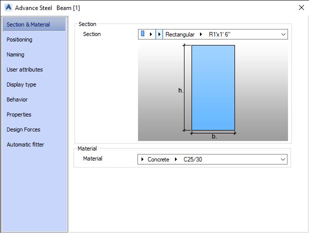
Section Area
You have the option to specify the Section Class, Section Type, and Section Size of the beam. You can choose the beam class from the Concrete Precast or Standard Profiles.
Material Area
Specify the material type and grade of your concrete beam.
Positioning Tab
Specify the location and orientation of your beam in relation to the system axis. Select the radio buttons to specify the system axis at the center, corner points, or midpoints of the beam:
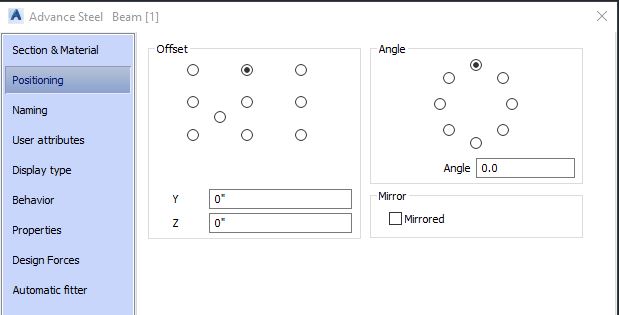
Angle Area
You can rotate your beam by a standard angle or enter a custom value in the Angle edit box.
Mirror Area
Mirror the beam around its vertical axis.
Naming Tab
In the Naming tab, you can specify the naming and BOM (Bill of Materials) information for your concrete beam. Normally, Advance Steel automatic numbering tools are used, but you can override some of the options in this tab.
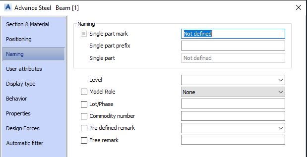
Naming Area
Single part mark and prefix for the single part mark to be assigned to the concrete beam.
Level
Select the level at which the beam is inserted (it will display Structure 1 value if there are no levels defined)
Model Role
The model role controls how the structural member is documented, dimensioned, and labeled in the detail drawings. You can select the Model Role check box and select the role type as the concrete beam from the drop-down menu.
Lot/Phase
You have an option to assign a lot or phase to the concrete beam.
Commodity Number
You have an option to assign a commodity number to the concrete beam.
Pre Defined Remark
Advance Steel allows you to save specific remarks about the structural members in the Notes table of the AstorBase.mdf file. Those remarks can be selected from this list. By default, the AstorBase.mdf file is stored in the ProgramData\Autodesk\Advance Steel2021\\Steel\Data folder. By default, the Notes table has four entries, but you can add more entries if required. Once you edit the entries in this database file, you need to start the Update Defaults button from the Home ribbon tab > Settings ribbon panel. The new remarks will be displayed in the Pre Defined Remark list.
Free Remark
Add any other remark if you wish here.
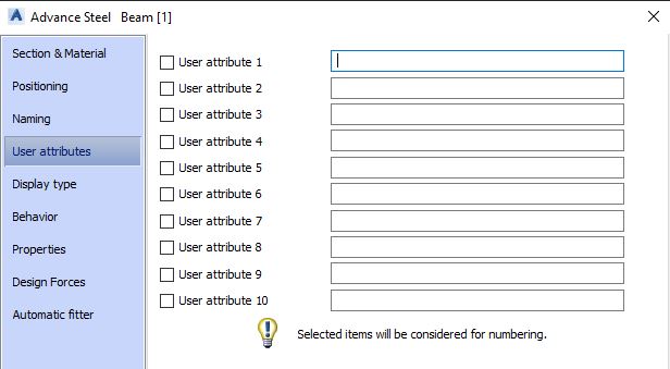
User Attributes Tab
Specify additional user-defined attributes which can be displayed in the title block while generating the detail drawings.
Display Type Tab
Control the representation of the concrete member in the drawing window.
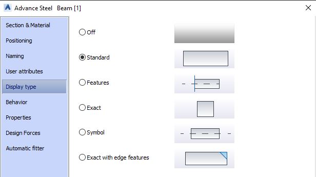
Standard
Default option. The beam and the system axis are displayed. Recommended for large structural models.
Features
Used when some cut features on the concrete are created. The edges of the object used to create the cut feature also will be displayed.
Exact
It is used to show the exact representation of the beam.
Symbol
The beam is turned off. The system axis is displayed only.
Exact With Edge Features
The exact representation of the beam, including the edge features such as fillets and chamfers.
Behavior Tab
Define how this concrete beam will be used in other Advance Steel operations.
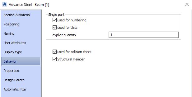
Used for Numbering
When checked, it will be used for single-part numbering.
Used for Lists
When checked, it will be used for various parts lists and BOM (Bill of Materials).
Explicit Quantity
Used to specify the quantity of the concrete beams required. By default it is 1, however, you can increase the quantity.
Used for Collision Check
When selected it will be a part of the collision check process.
Structural Member
When checked, the beam will be treated as a structural member in the current model.
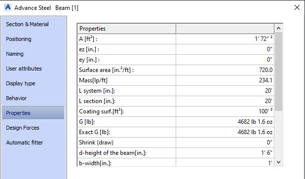
Properties Tab
Various physical, geometric, and section properties are displayed.
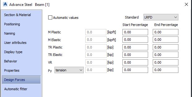
Design Forces Tab
Specify the values for the design forces to be considered for the beam. The values can be specified based on the LRFD or ASD standard. When the Automatic Values check box is selected, Advance Steel will define these values automatically.
Automatic Fitter Tab
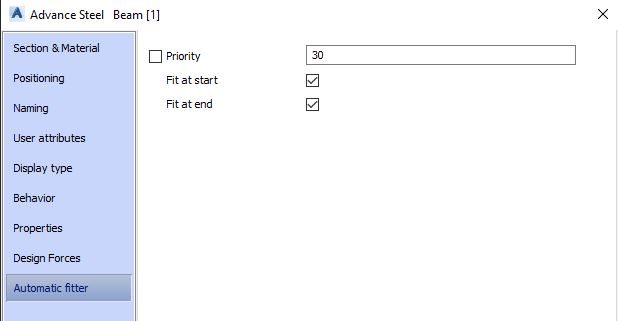
Priority
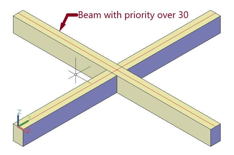
Option important at the intersection of beams. Normally, the first gets priority over the second one, which allows the first to remain a continuous element. If you want the second beam to be a continuous element, raise its priority value over 30. By doing so, the second beam will become a continuous element.
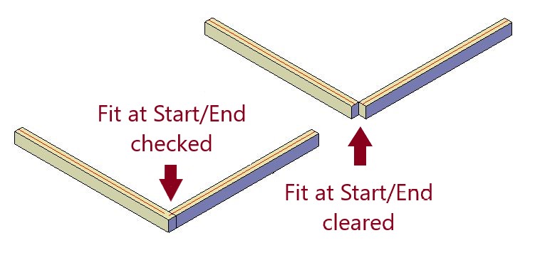
Fit at Start / Fit at End
Controls how the beam with priority will appear at the corner intersection of another beam. By default, both boxes are selected, and as the result, the beam with the priority is extended at the corner.