When you start working on a new project in Advance Steel, the first thing you will most likely need to do is create a grid. You will need this grid to place and organize all the structural members you are going to create in your model. The structural grid is the base of your project, and there are a few ways in Advance Steel to create the Grid. In Advance Steel, a grid is an auxiliary object and is used as a reference when creating the model. There are five tools in total for creating grids.
Advance Steel Grid Lines
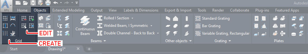
Advance Steel made it possible to draw grid lines in five different ways, using five different tools specially designed for it. All five tools required to create a grid in can be found in the Objects tab > Grid panel. Here you will also find tools to Edit Grid Axes just right from Create Grid.
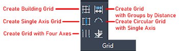
Using the tools from this menu tab, it is possible to choose one of five methods to create a grid:
- Create Building Grid
- Create a Single Axis Grid
- Create a Grid with Four Axes
- Create a Grid with Groups by Distance
- Create a Circular Grid with a Single Axis
Create Building Grid
To access this tool, you have two options:
You can access it from the OBJECTS tab as shown above, or the other option is to access it from the HOME tab.
HOME Tab > OBJECTS Panel > Building Grid Icon.
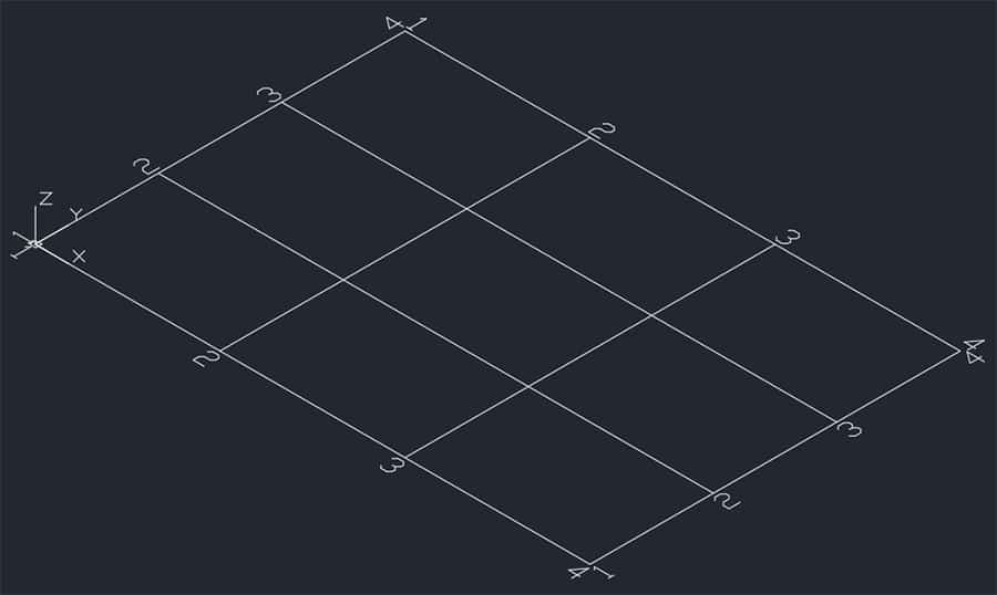
The choice is yours. This tool will help you create a 4×4 grid. You need to specify two diagonally opposite corners when creating the grid this way.
You will create the grid on the XY plane of the currently chosen UCS (User Coordinate System).
When you choose the tool with the single left click of your mouse, the prompt will appear:
Please define two diagonal points for grid, origin: _
So now you have a chance to specify where you want to place the lower-left corner of your grid. You can enter for example 0,0. You can also click on any point directly on the screen. Once your first point is determined, another message will appear:
Second point: _<60’,40’>:_
Now, you can specify a second point by entering new values or by clicking on any point in your drawing area, or you can also click ENTER to accept the default values. Once the second point is specified, the new grid will appear.
Here is an example of the grid drawn from 0,0 point using default values:
Create Single Axis Grid
You can access this tool from the OBJECTS tab > GRID panel > Single Axis Grid Icon
Using this tool, you can create just one grid along the desired direction. Once you left-click on the tool, the prompt will appear:
Please define the endpoints of the grid line. Start point: _
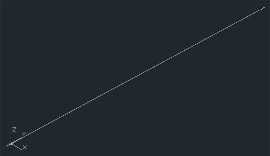
Now you can specify the start point of your axis either by clicking in the drawing area or entering an X, Y value, for example, 0,0. Now, your starting point is established, and it is time to specify the endpoint of this grid axis either by entering the length and angle, for example 30’<45, or by clicking on the point in the drawing area.
Here is an example of the grid axis drawn from 0,0 point:
Create Grid With Four Axes
To access this tool, go to the OBJECTS tab > GRID panel > Grid with 4 axes Icon
Using this tool, you won’t create a single grid axis as described in the method above but four parallel axes at once. The distance between the axes will be identical.
Once you left-click on the tool, the prompt will appear:
Please define the endpoints of the grid line. Start point:_
You can click on any point in your drawing area or you can specify numerical X, Y values like 0,0, for example. As soon as your start point is set, the next prompt will appear:
End Point:_
Now, you have a chance to specify the length value and angle of the axes in the format 20’<90 or by clicking on the point in the drawing area. The next thing to do is specify the overall distance of all four axes. For example, if you wish to have 25’ spacing in between them, then you need to enter 75’ (because 3 spaces in between the four axes x 25’ = 75’).
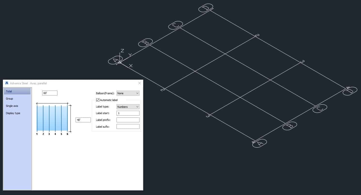
You can also click on a point on the screen and modify the axes in the dialog box that opens after you’re done clicking:
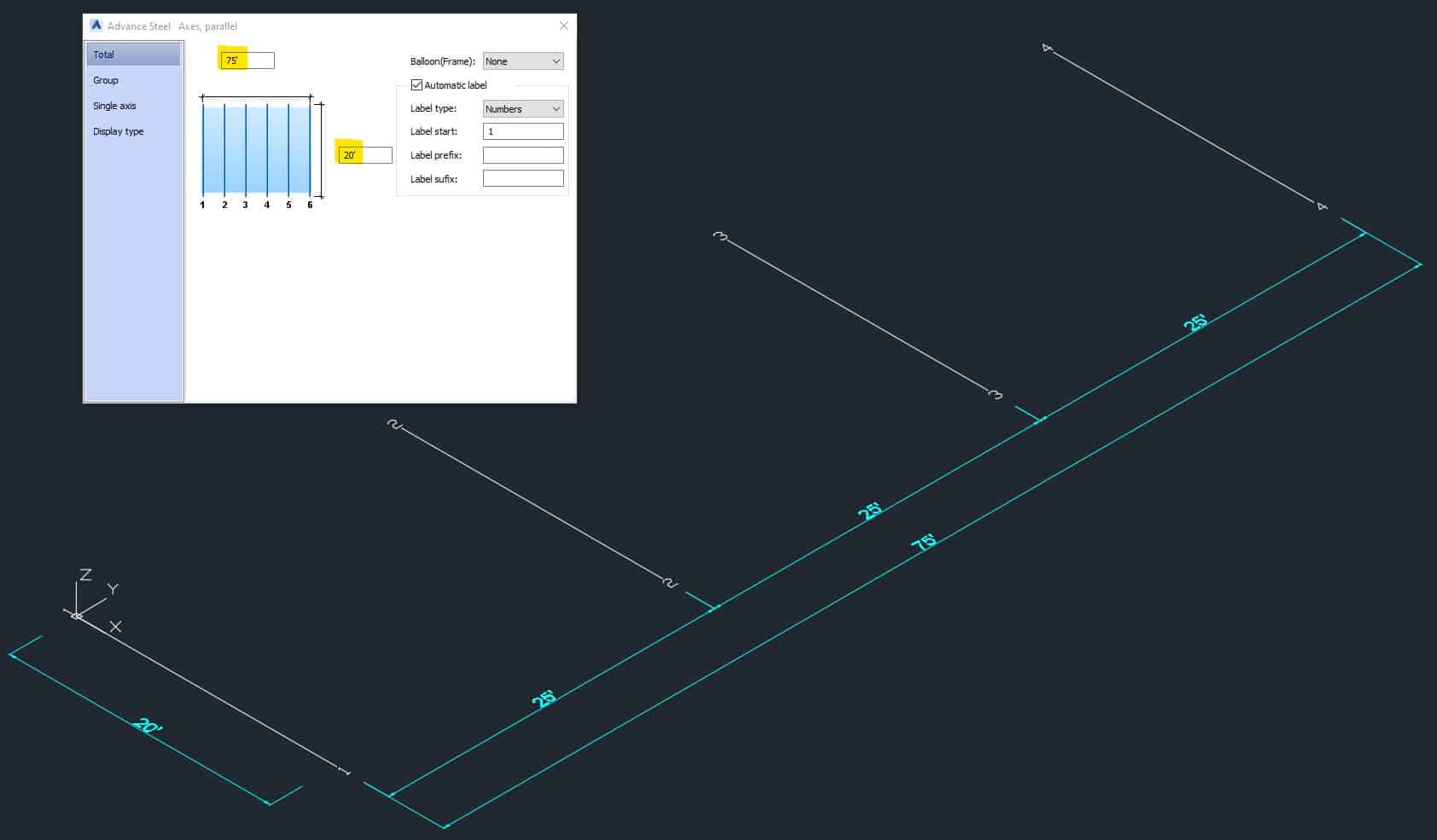
Here you can specify the overall distance between the first and the last axes (value at the top highlighted in yellow), as well as the length of the axis (also highlighted in yellow, value on the right-hand side). In the “Group” section of this dialog box, you can specify the number of equally spaced axes as shown in the screenshot below:
Once you are done editing your grid, close the dialog box. Here is an example of the ready Four Axes Grid 20’–0” long and with grid spacing of 25’–0” on center.
Create Grid with Groups by Distance
To access this tool, go to the OBJECTS tab > GRID panel > Grid with groups by distance
Click the tool on the ribbon. Now, you can specify the grid start point by left-clicking anywhere on the screen in the drawing area space, or by entering a numeric X, Y value after the prompt on the screen appears:
Please define the endpoints of the grid line. Start point:_
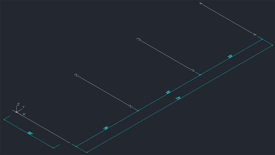
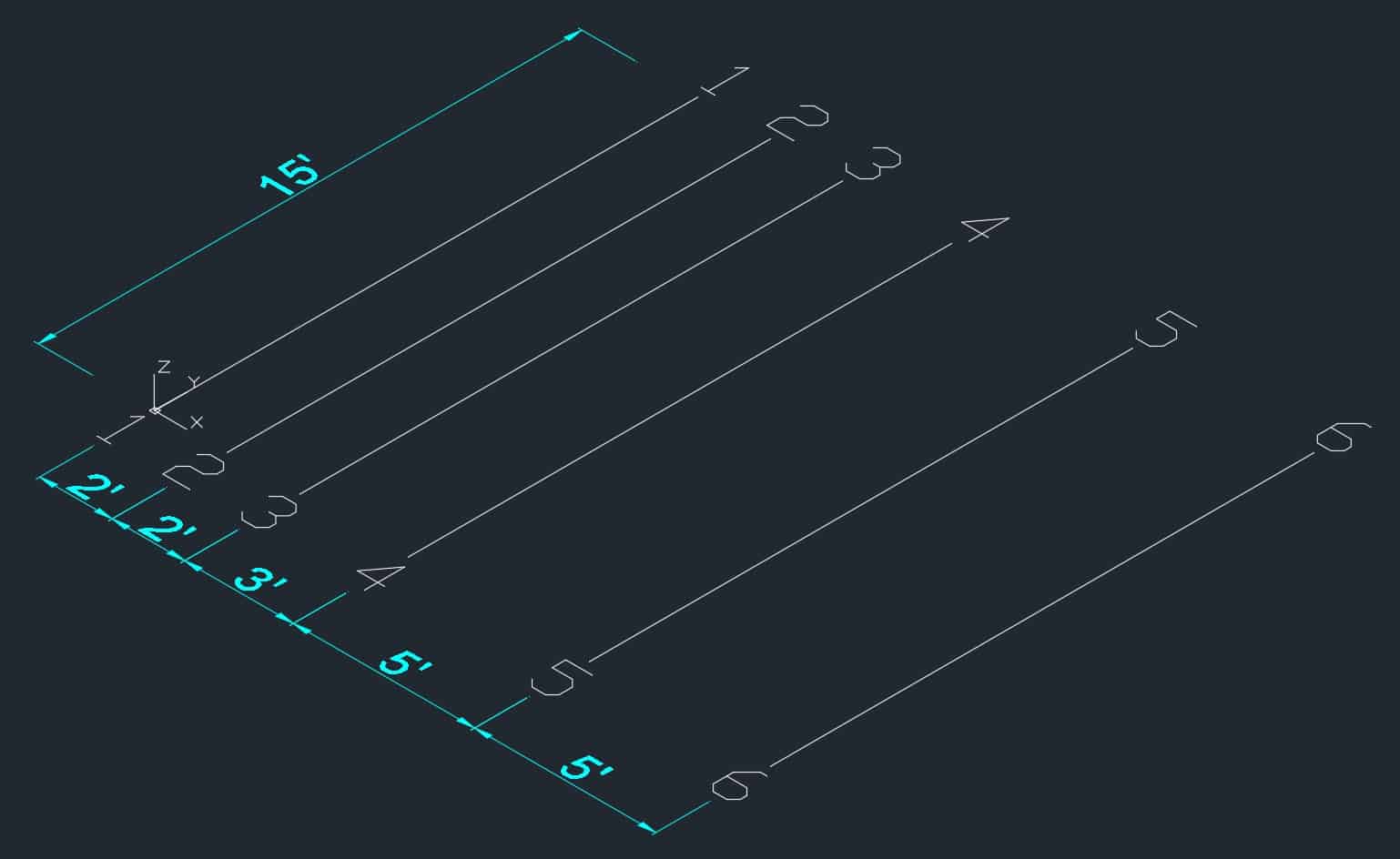
Then, you need to enter the numeric value for the endpoint (the length of the grid axis) – for example, 15’ or click on the point in the drawing area.
The next thing to do is specify the sequence of the axes by entering spacing in between, confirming by pressing ENTER once. For example:
2’ ENTER 2’ ENTER 3’ ENTER 5’ ENTER 5’ ENTER ENTER
At the end of the sequence, you need to press ENTER twice – once to confirm the value and the second time to confirm the end of the sequence. Your grid will be created as follows:
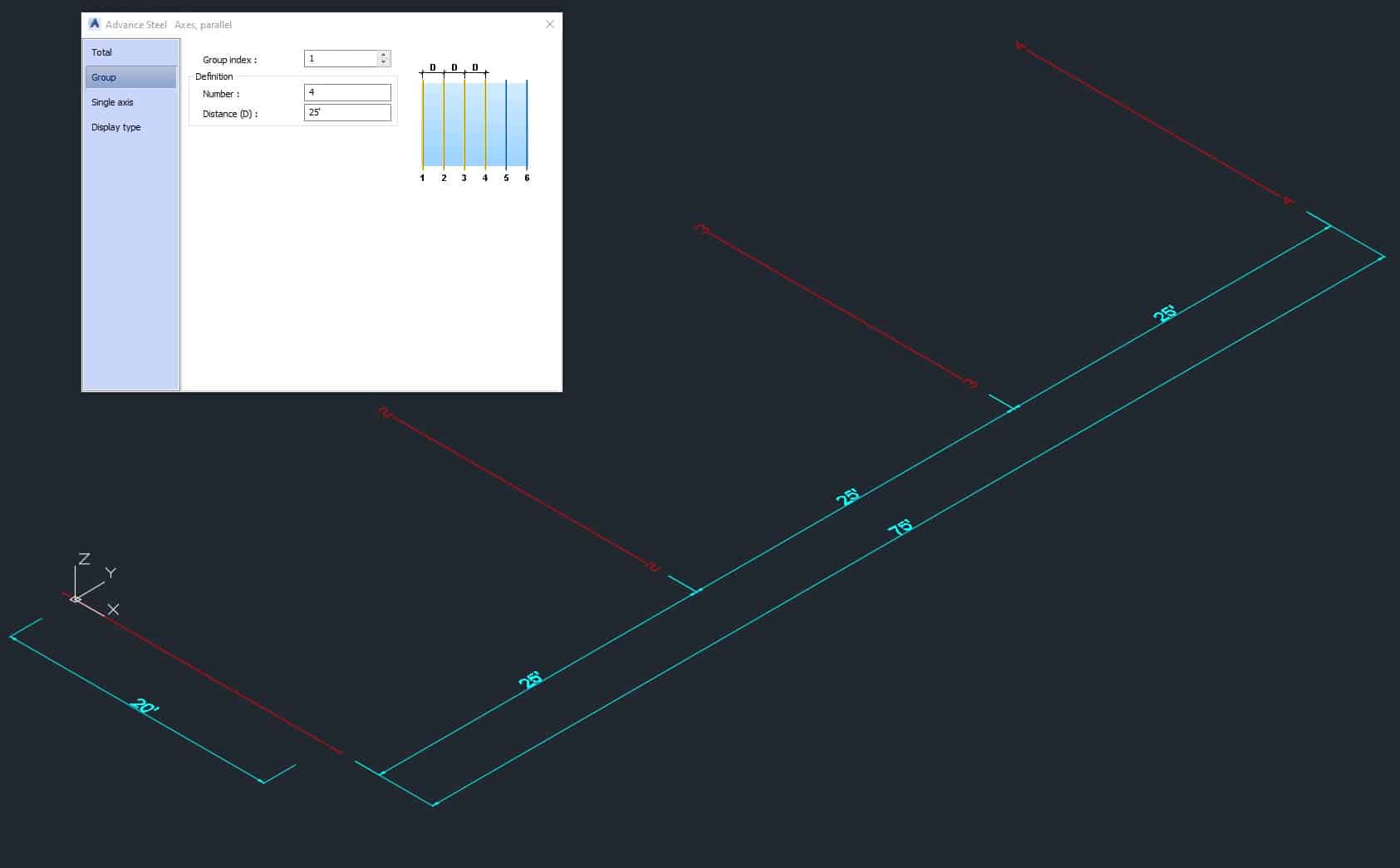
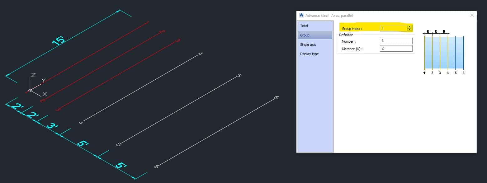
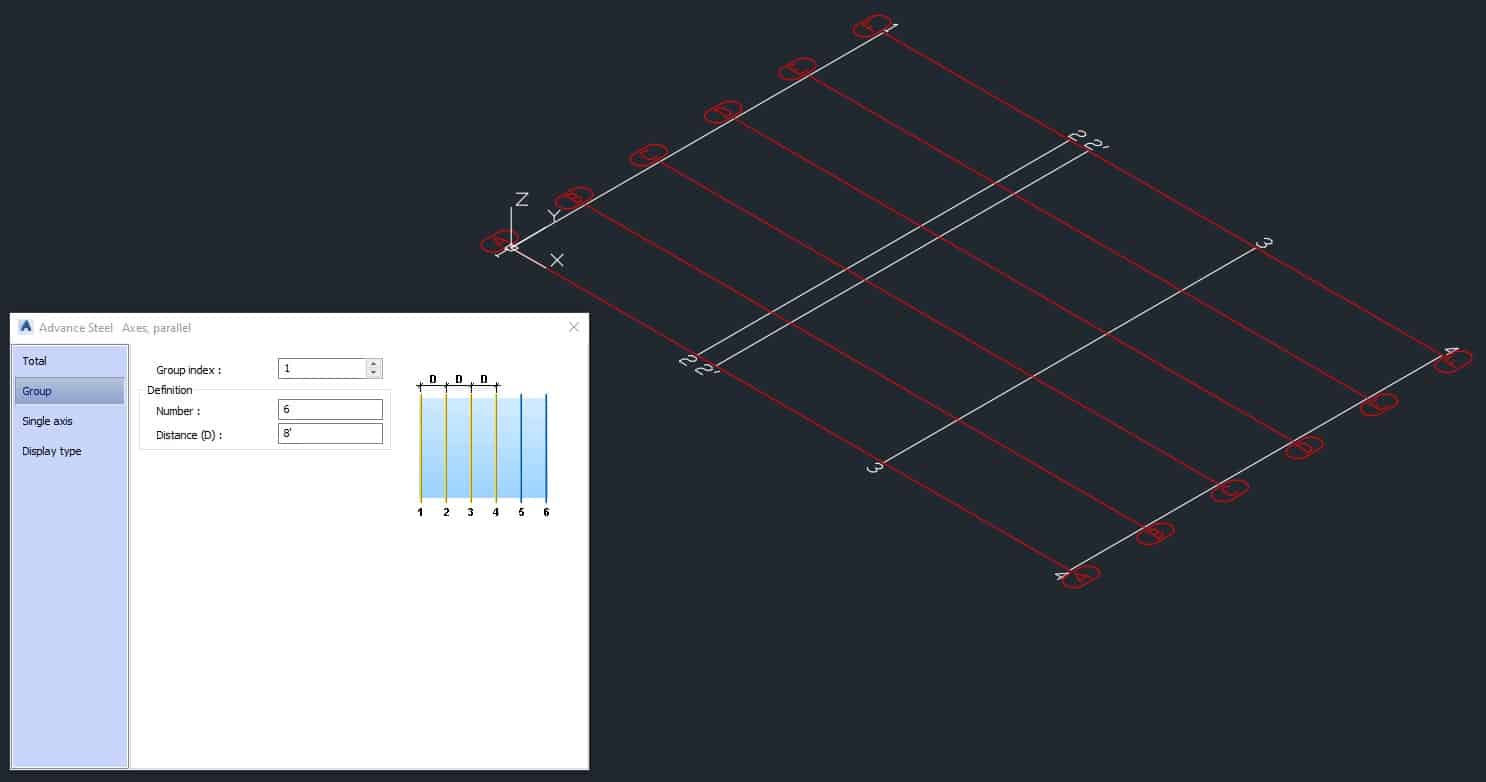
Once you are done entering all the values, a dialog box will open, giving you a chance to adjust the entered values. A grid axis with the same distance in between them will be grouped. The Group Index is the first on the top; use arrows to navigate between the groups. They will highlight in red in your grid drawing as follows (Group Index is highlighted in yellow):
Create Circular Grid with Single Axis
To access this tool, go to the OBJECTS tab > GRID panel > Curved Grid with Single Axis
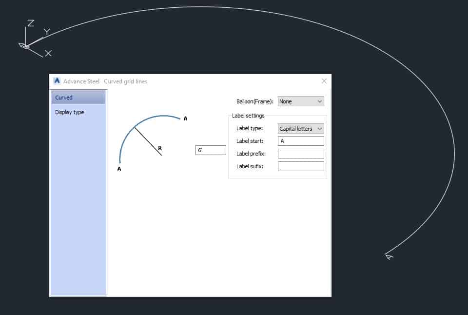
When using this tool, first you must specify the start point, then the endpoint, and the point located on the curve. You can do it by entering numerical values or by clicking on the desired points on the screen in the drawing area. Upon entering all the values, the dialog box will open where you can make adjustments to your grid.
Edit And Modify Grids
Great! You have just created a grid using one of the five methods described above, but what if you want to modify your grid? Well, the simplest solution is to double-click on one of the axes. A dialog box will open where you have a chance to tweak all the values. You can number the axis or use capital or small letters as grid labels.
The other cool feature is that you can specify if your grid labels should be “Balloon Style” or not.
You can also set label prefixes or suffixes.
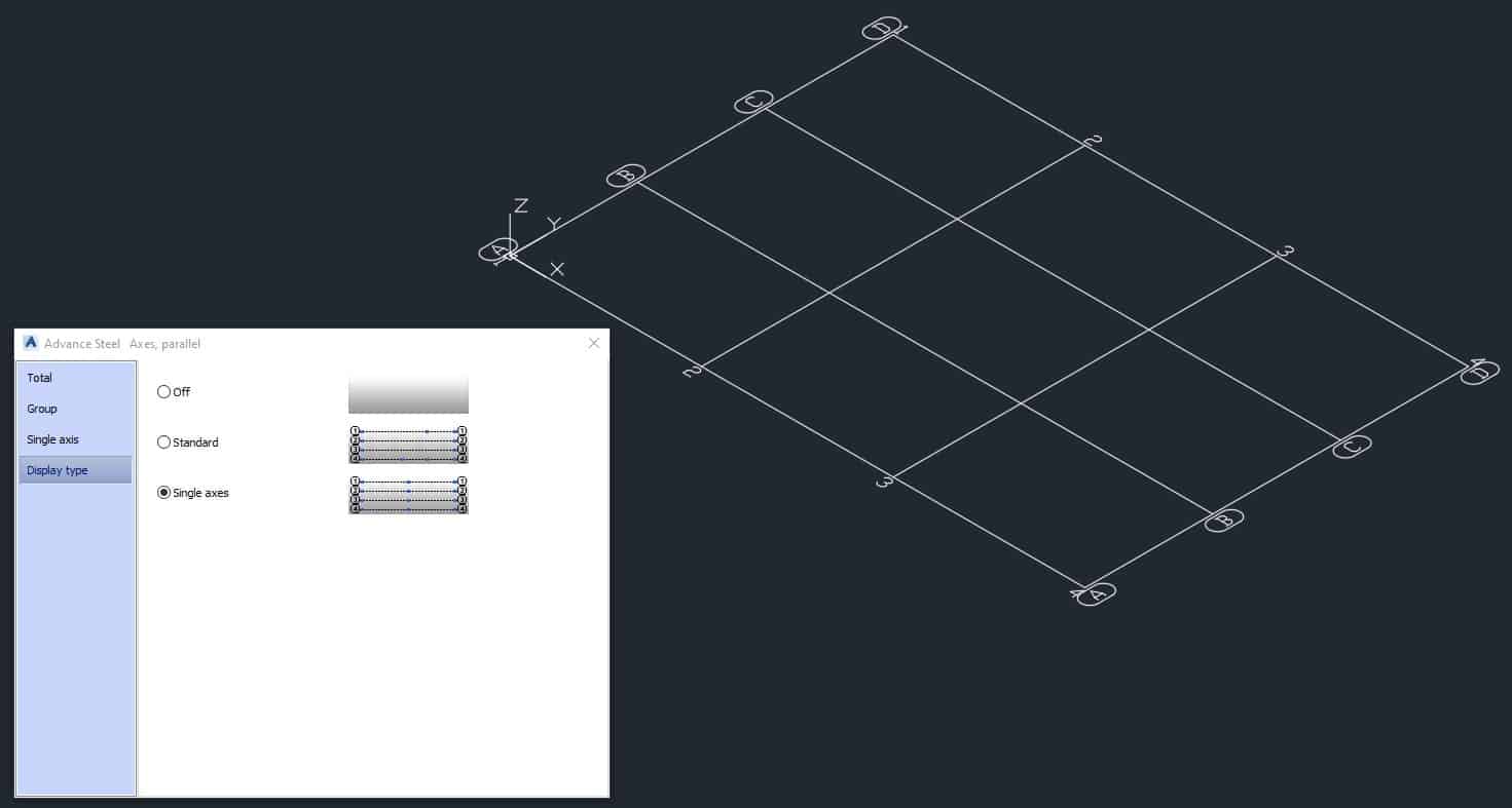
By going to “Display Type” and changing it from “Standard” to “Single Axes”, you can move any single grid in any direction.
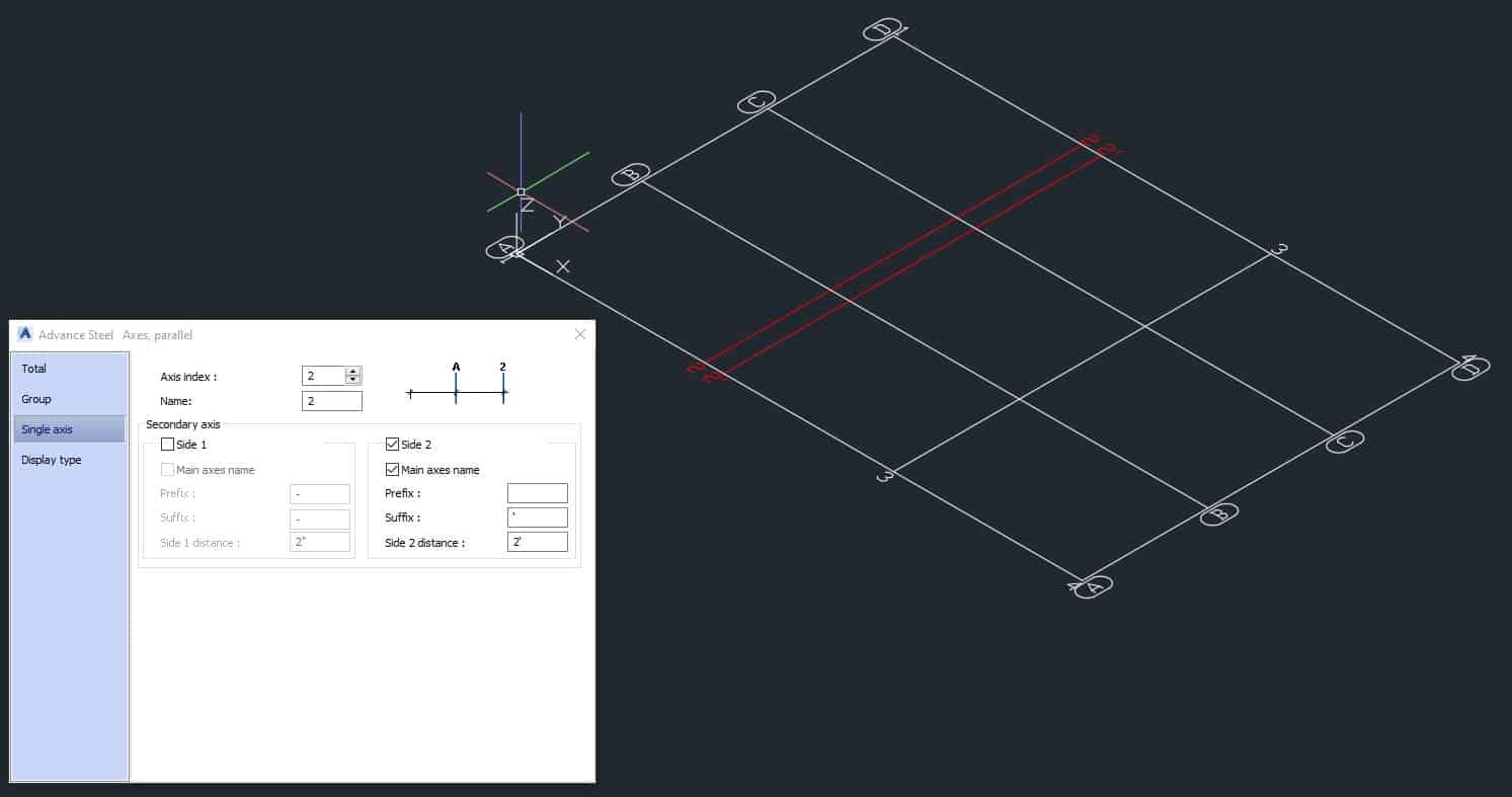
When you go to the “Single Axes” options, you have a chance to add additional sub-axes on the left or on the right-hand side of the main axis. Here you can use a prefix and suffix.
In the “Group” section, you can change the total number of axes.
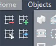
Add & Remove, Trim & Extend Axes
To access these tools, go to the OBJECTS tab > GRID panel (right side of this panel)
You can perform actions such as adding, deleting, trimming, and extending your axes with those tools.
Deleting Grid Axes
If you choose the Delete icon, the prompt will appear:
Please select the grid at the axis to be deleted:_
Then, you need to select the axis you want to get rid of and click ENTER. The axis will be gone immediately.
Adding Grid Axes
Use this tool if you want to add one or more gridlines to an existing grid. When you choose the Add icon from the menu, a prompt will appear:
Please select the grid axis after which the group is to be inserted:_
Now, select the grid line and press ENTER. Then the question will pop up:
Number of axes:_
Enter the desired quantity of the axes to be added to your grid. Press ENTER. And the last question will appear:
Distance between axes:_
Answer this prompt and press ENTER. New axes will be added to the right side of the initially selected gridline.
Trimming Grid Axes
If you wish to trim one or more grid axes, you can do it using the Trim tool and boundary objects. Boundary objects are used as the cutting edges. When you select this tool, the prompt will appear:
Please select boundary objects:_
Now, select objects that will serve the purpose of cutting the edge. The nest prompt will appear:
Select axis that is to be cut: _
Now, select the axis that needs to be trimmed. The portion of the undesired axis will be gone.
Extending Grid Axes
Use this tool if you wish to extend one or more grid axes, using one or more boundary objects. When you select this tool, this first prompt will appear:
Please select boundary objects:_
Select the object to which your grid axes need to extend and press ENTER. The next prompt will appear:
Select axis that is to be extended:_
Select the axis that you need to extend and press ENTER.
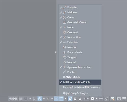
Extra Tip
When working with grids in Advance Steel, make sure to turn on the snap option “Grid Intersection Points”:
Conclusion
This is about everything you need to know about the grid system and its axes in Advance Steel. The main thing is that it is easy to draw and modify and has all the options readily available for modification to your project needs.
This concludes the Grid Lines Tutorial. Good luck using all the methods and tools described above. If you find this article valuable, please subscribe to my blog to be notified when I publish a new article.
If you are interested in upgrading your hardware or software, make sure to check out My Toolbox article, where I share information about the tools I use and special discounts you can use as well.
If you are into Advance Steel –