In Advance Steel, it is possible to create workplanes that act as the modeling planes. Normally, in Advance Steel, workplanes are created automatically when you create levels. But if you desire to manually create workplanes, you can access this option in the Workplanes pane of the Project Explorer window.

How To Create New Workplane?
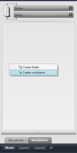
To create a new workplane, simply right-click in the Workplanes pane and select the option Create Workplane from the menu as shown below:
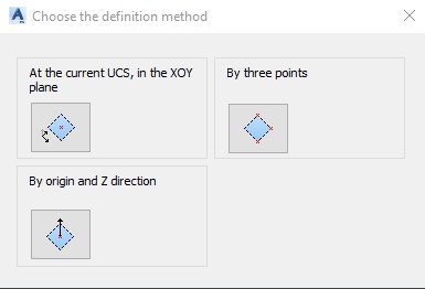
Upon choosing the option Create Workplane, the Choose the Definition Method dialog box will appear with three available options to choose from:
- At the current UCS, in the HOY plane
- By three points
- By origin and Z direction
See the picture on the side:
And below, you can find a detailed description of all three methods:
Create Workplane at the current UCS, in the XOY plane
- Go to Project Explorer> Workplanes pane, right-click in the pane, and the menu will appear.
- Select Create Workplane, and the Choose the Definition Methodwill appear.
- Choose from the menu options: At the Current UCS, in the XOY Plane
- You will be asked to select a point. Select a point in the model where you want to create the workplane.
- You will be asked to Enter the Nameof the new workplane. Enter a new name and press ENTER.
- A dashed rectangle will be drawn, representing your new workplane. The new workplane with a new name will appear in the workplane pane. The same workplane name will be listed as well on the dashed rectangle representing the workplane in the graphic window.
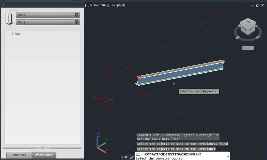
- To associate objects to your new workplane, right-click on the workplane name in the Workplanespane and select Attach Elements from the menu. Then, select the object you want to tie to this workplane.
- Next you will be asked to Select the Geometry Points. Red points will be displayed at the end nodes of the selected object(s).
- Select all the points you want to attach to the workplane and press ENTER.
- All the objects with points selected will now be associated to your workplane.
Tips:
- When you have objects bound to a workplane, it won’t be possible to extend them below the workplane level.
- You can associate objects to different workplanes at the top and bottom. As a result, the height of the associated objects will be confined within the gap of the two workplanes.
Create Workplane By Three Points
- Go to Project Explorer> Workplanes pane, right-click in the pane, and the menu will appear.
- Select Create Workplane, and the Choose the Definition Methodwill appear.
- Choose from the menu options: By Three Points.
- You will be asked to select the first point. Select the first point in the model to locate the Workplane.
- You will be asked to select the second point. Select the second point to locate the Workplane.
- You will be asked to select the third point. Select the third point of the Workplane.
- You will be prompted to specify the Workplane Name. Type the name for the new workplane and hit ENTER.
- A dashed rectangle will appear. The rectangle represents the location of the Workplane.
- The name will appear on the dashed rectangle and in the Workplanes pane.
- To associate objects to your new workplane, right-click on the workplane name in the Workplanespane and select Attach Elements from the menu. Then, select the object you want to tie to this workplane.
- Next you will be asked to Select the Geometry Points. Red points will be displayed at the end nodes of the selected object(s).
- Select all the points you want to attach to the workplane and press ENTER.
- All the objects with points selected will be now associated to your workplane.
Create Workplane By Origin and Z Direction
- Go to Project Explorer> Workplanes pane, right-click in the pane, and the menu will appear.
- Select Create Workplane, and the Choose the Definition Methodwill appear
- Choose from the menu options: By Origin and Z Direction.
- Select the point in the model to locate the Workplane. You will be asked to select the first pointfor the direction. Specify this point.
- You will be asked to specify the second pointfor the direction. Using, for example, polar tracking or some other method, specify the second point for the direction.
- You will be prompted to specify the name of a new Workplane. Enter the name and press ENTER.
- A dashed rectangle will appear. The rectangle represents the location of the Workplane in space.
- The name will appear on the dashed rectangle and in the Workplanes pane.
- To associate objects to your new workplane, right-click on the workplane name in the Workplanespane and select Attach Elements from the menu. Then, select the object you want to tie to this workplane.
- Next you will be asked to Select the Geometry Points. Red points will be displayed at the end nodes of the selected object(s).
- Select all the points you want to attach to the Workplane and press ENTER.
- All the objects with points selected will be now associated to your Workplane.
This concludes the Workplanes Tutorial. Good luck using all the methods and tools described above. If you find this article valuable, please subscribe to my blog to be notified when I publish a new article.
If you are interested in upgrading your hardware or software, make sure to check out My Toolbox article, where I share information about the tools I use and special discounts you can use as well.
If you are into Advance Steel –