
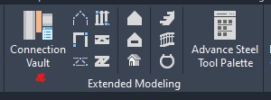
When you are detailing for steel, you will need to use the Gusset Plate most likely sooner rather than later. In this article, I will go over a few of the most common methods in Advance Steel when inserting the gusset plate. To access gusset plates, go to Home > Extended Modeling > Connection Vault.
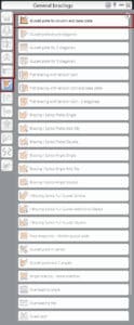
The connection menu will open. Go to General Bracings as shown below:
Save a Pin to your Pinterest board Advance Steel Tips & Tricks:

Gusset Plate To Column And Base Plate Joint
You will use this connection type to connect a gusset plate and a bracing section to a column and a base plate or column and a secondary beam. The bracing sections that you can use for this joint include angles, channels, flat bars, and hollow sections. When you activate this tool, you will be asked to select the column beam. Once you select the required element, press ENTER. Now, you will be prompted to select the secondary beam or the base plate. Select and press ENTER. Now, you will be asked to select the diagonal beam – the bracing section. Once you select the diagonal beam and confirm your selection by pressing ENTER, a dialog box will open with the Properties category > Properties tab.
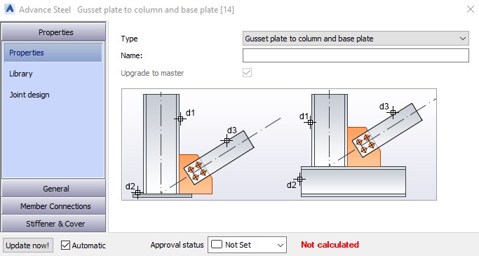
This is one of the most common bracing connections. Save your preferred settings in the Library tab of the dialog box for future use.
GENERAL - Gusset Plate Shape Tab
When you access the general category in then left pane of the dialog box, the Gusset Plate Shape is the first option.
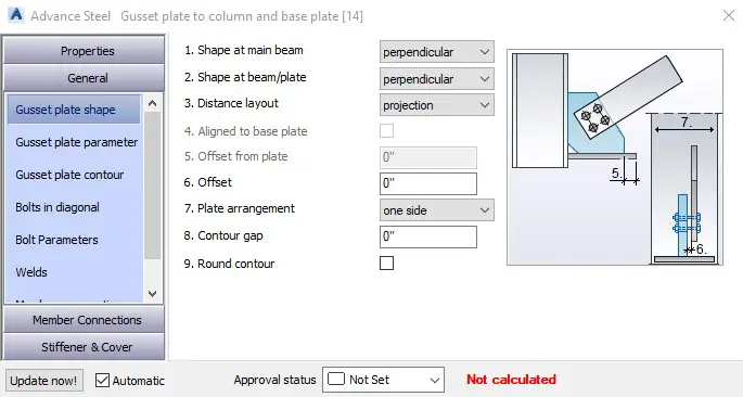
Here are all the available options:
[1] Shape At Main Beam
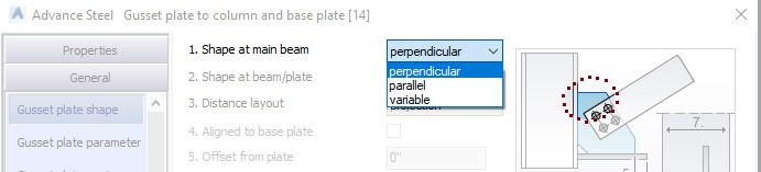
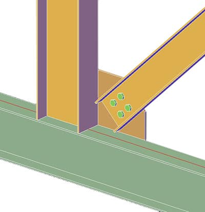
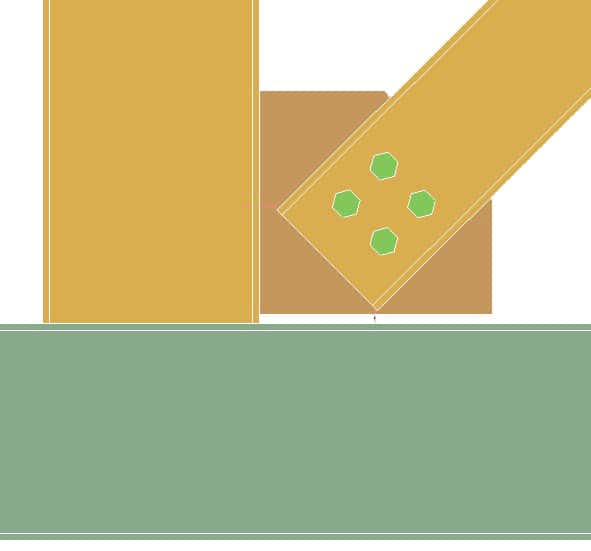
You can specify the shape of the gusset plate at the main beam. Default option: Perpendicular is selected. As a result, the plate is inserted perpendicular to the main beam/column as shown in the picture below:
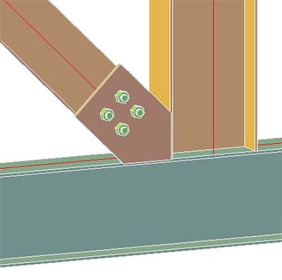
When you select Parallel from this drop-down list, the gusset plate will be cut parallel to the bracing as shown below:
[2] Shape At Beam/Plate
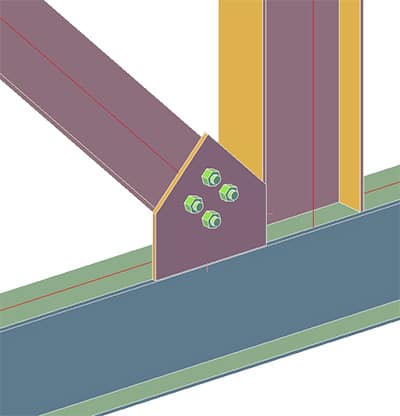
In this drop-down menu, you can define the shape of the gusset plate at the secondary beam or base plate. The options are the same as described above. The picture below shows perpendicular on both sides:
[3] Distance Layout
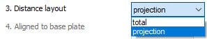
You can specify if you want to define the layout of the plate using projections or total distance values.
[4] Align To Base Plate
When inserting the gusset plate perpendicular to the base plate, checking this box will align the lower width of the gusset plate to the edge of the base plate.
[5] Offset From Plate
This edit box is only available if you have the Align to Base Plate box selected. Enter the offset between the gusset plate and the edge of the base plate here.
[6] Offset
Enter the offset value between the face of the bracing and the gusset plate.
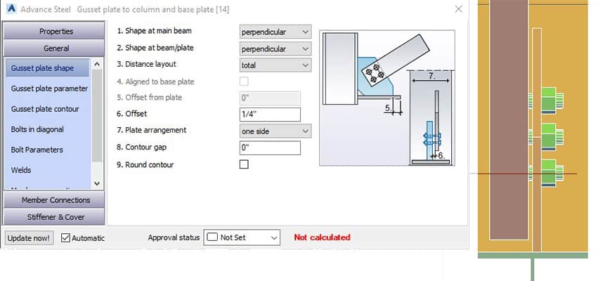
[7] Plate Arrangement
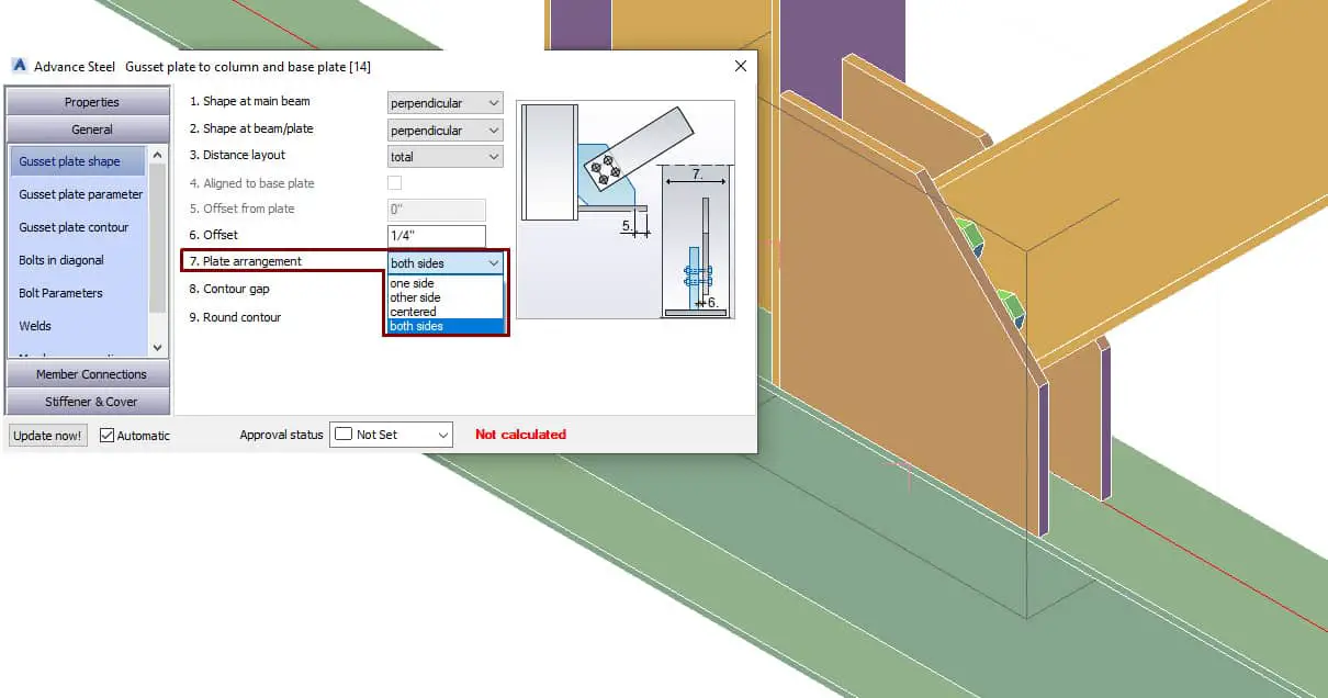
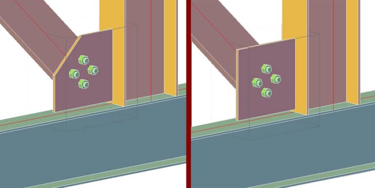
Specify the arrangement of the gusset plates around the bracing section. Plate arrangement – both sides is shown in the picture above.
[8] Contour Gap
Specify the value of the contour gap here.
[9] Round Contour
Check this box to make sure the contour is rounded.
GENERAL - Gusset Plate Parameters Tab
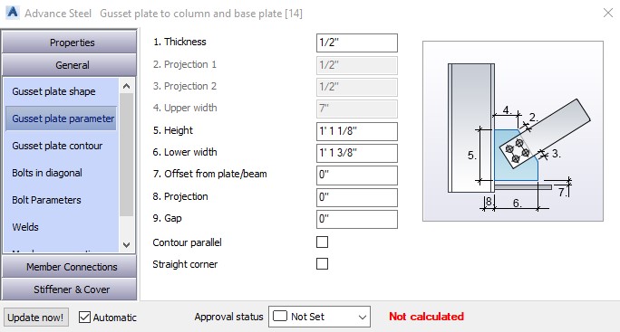
You can specify all the parameters of your gusset plate.
[1] Thickness
Specify the thickness of the gusset plate.
[2] Projection 1
This option is only available when the Projection is selected from the Distance Layout drop-down list from the Gusset Plate Shape tab. You can specify the distance between the bracing section and the top edge of the gusset plate. This dimension is labeled “2” in the Parameter Preview Window on the right side of the dialog box.
[3] Projection 2
This option is only available when Align to Base Plate is selected when the Distance Layout check box is not selected from Gusset Plate Shape tab. You can specify the distance between the bracing section and the right edge of the gusset plate. This dimension is labeled “3” in the Parameter Preview Window on the right side of the dialog box.
[4] Upper Widith
Specify the upper width of the gusset plate. This dimension is labeled “4” in the Parameter Preview Window on the right side of the dialog box.
[5] Height
Only available when Variable is selected from the Shape at Main Beam drop-down list in the Gusset Plate Shape tab. Enter the height of the gusset plate in this edit box. This dimension is labeled “5” in the Parameter Preview Window on the right side of the dialog box.
[6] Lower Width
Only available when Variable is selected from the Shape at Base Plate drop-down list in the Gusset Plate Shape tab. Enter the lower width of the gusset plate. This dimension is labeled “6” in the Parameter Preview Window on the right side of the dialog box.
[7] Offset From Plate/Beam
Enter an offset value between the gusset plate and the base plate (or secondary beam). This dimension is labeled “7” in the Parameter Preview Window on the right side of the dialog box.
[8] Projection
Define the penetration of the gusset plate inside the column. This dimension is labeled “8” in the Parameter Preview Window on the right side of the dialog box.
[9] Gap
Use this in combination with the Projection edit box. Define the gap between the gusset plate and the column opening for penetration.
[10] Contour Parallel
Check this box to ensure the contour is parallel.
[11] Straight Corner
Select to insert the gusset plate with a straight corner.
Unchecked – Checked
GENERAL - Gusset Plate Parameters Tab
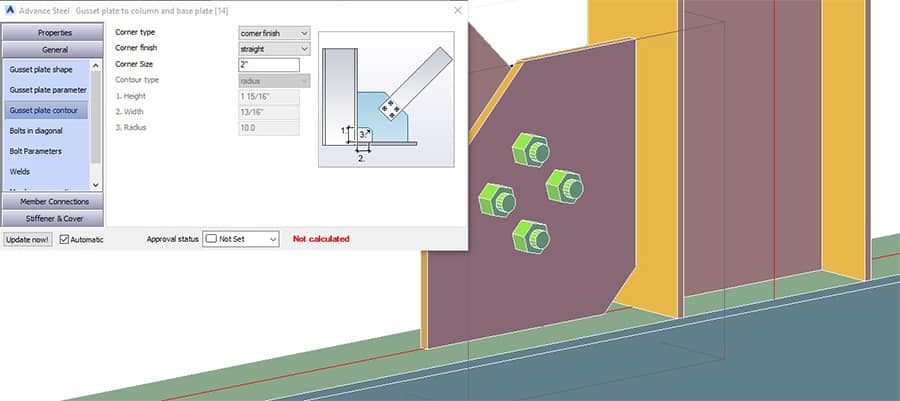
- Define the parameters related to the gusset plate contour. You can select the contour from the Corner Typedrop-down. By default, “None” is selected. The following options are available:
- Corner Finish
- None
- Straight
- Concave
- Convex
- Contour
- Radius
- Angle
You can enter contour parameters (height, width, radius) below the drop-down menu.
GENERAL - Bolts In Diagonal Tab
This tab is used to define the options of the bolts in the bracing section:
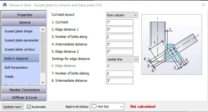
[0] Cut Back Layout
This drop-down list is used to specify whether the bracing cutout will be defined from the column face or the endpoint of the column system axis.
[1] Cut Back
Enter the cut back value. This dimension is labeled “1” in the Preview Window on the right side of the dialog box.
[2] Edge Distance 1
Distance between the end of the bracing member and the center of the first bolt. This dimension is labeled “2” in the Preview Window on the right side of the dialog box.
[3] Number Of Bolts Along
Quantity of bolts inserted along the bracing section.
[4] Intermediate Distance
Enter the intermediate distance between the bolt centers along the bracing section. This dimension is labeled “4” in the Preview Window on the right side of the dialog box.
[5] Edge Distance 2
Distance between the end of the gusset plate and the center of the last bolt. This dimension is labeled “5” in the Preview Window on the right side of the dialog box.
[6] Settings For The Edge Distance
Specify where the bolt centers should be inserted. Available options: Center Line, Gauge Line, Edge. This dimension is labeled “6” in the Preview Window on the right side of the dialog box.
[7] Number Of Bolts Oblong
Specify the number of columns of bolts to be inserted in the other direction.
[8] Intermediate Distance
Specify the intermediate distance between the bolt centers in the other direction.
Gusset Plate At One Diagonal Joint
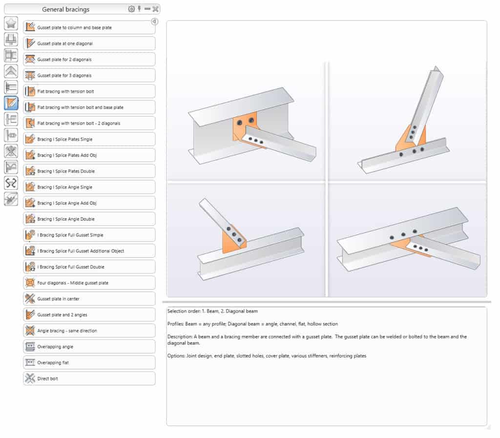
Similar to the previous joint with one difference –you do not need to select the base plate or the secondary beam.
Gusset Plate at Bracing Sections
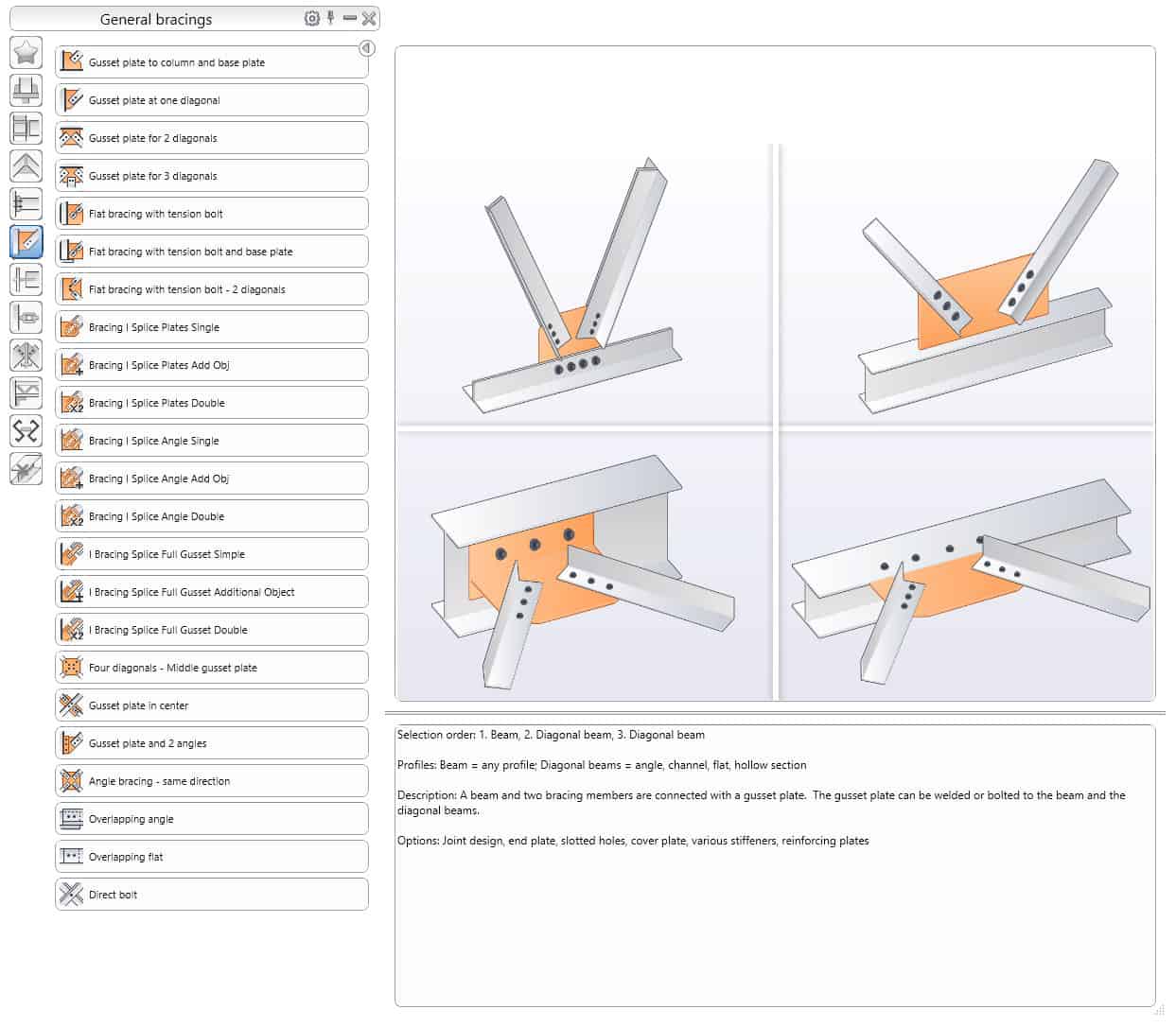
This joint is used to connect two bracing sections to a beam using a gusset plate.
Four Diagonals - Middle Gusset Plate Joint
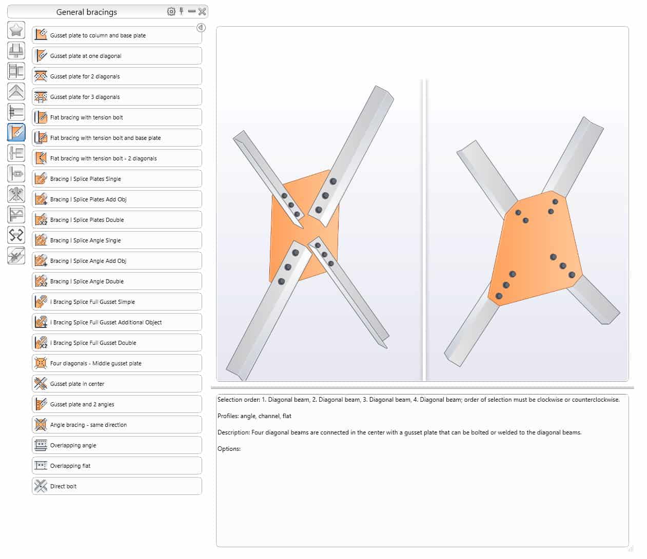
This is used to connect four diagonal bracing sections, using a gusset plate at the center.
This concludes the Gusset Plate Tutorial. Good luck using all the methods and tools described above. If you find this article valuable, please subscribe to my blog to be notified when I publish a new article.
If you are interested in upgrading your hardware or software, make sure to check out the My Toolbox article, where I share information about the tools I use and special discounts you can use as well.