If you want to start working in Advance Steel, if you want to learn how to detail steel for steel production – this is tutorial for you. I am sharing entire process of making a Steel Platform used by CTA Chicago Transit Authority for maintenance. I will show you entire procedure from setting up a new project to making a final set of drawings and then also how to make revisions to your project. In this article I will show you how to create a grid in Advanced Steel.
This is not a standard Advance Steel project, but because of that I have decided to share it with you. Once you get the idea how to detail this Platform – making any other project will appear very easy.
Save this Pin to your Pinterest Advance Steel board:
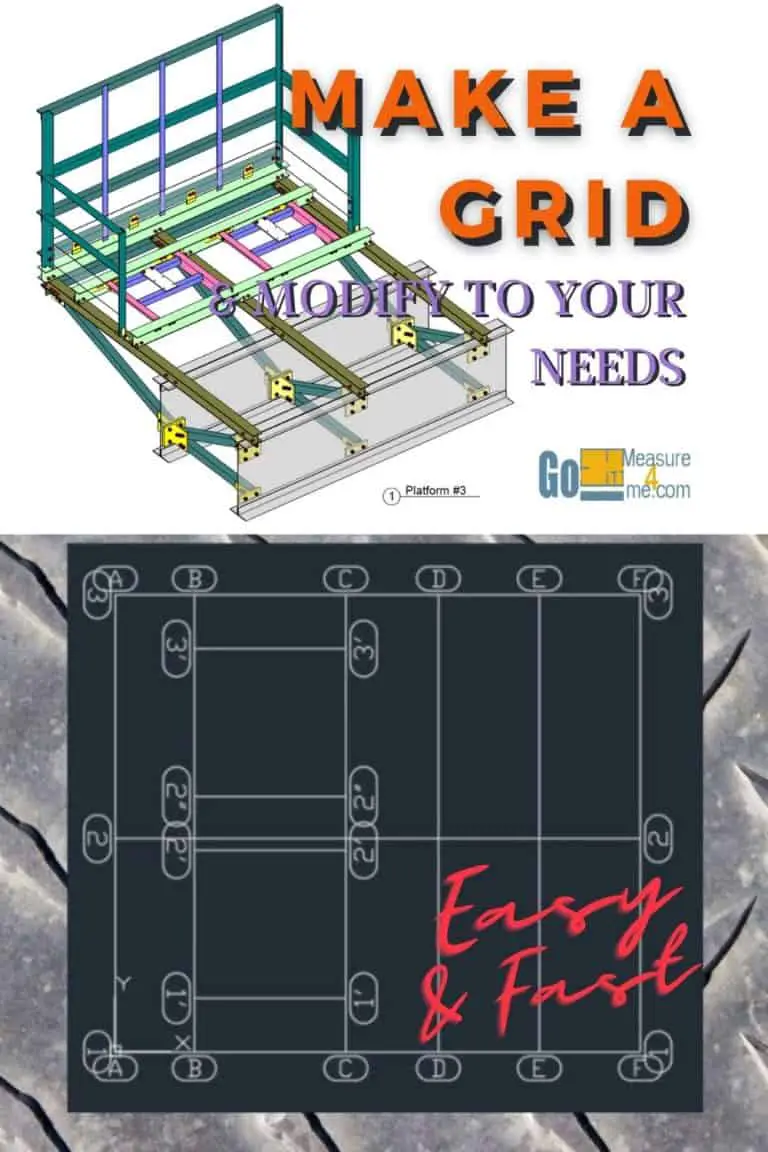
How To Place a Grid In Your Drawing Easy
You can watch entire video above on YouTube.
Here is the Completed Project File for you to download for free.
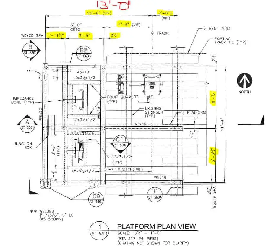
In this tutorial we are going to make a grid for this 13′-0″ x 11’4″ steel structure:
STEP 1 - Place A Grid In The Drawing
The plan does not have a grid system assigned so I am going to make my own grid for this project. The overall dimensions are 13’-0” x 11’-4”.
Go to the “objects” tab, then in the “Grid” panel click on the new grid, specify insertion point as 0,0. Then enter 13′ enter and 11’-4”, your new grid is placed in the project. Now click on the Top View in your 3D cube and then select the grid and double click it. Now let’s notify vertical grids. I have marked in yellow all the crucial dimensions to make the grid in the advance steel grid dialog box in the “Group” section enter number 6. As the number of grid lines, don’t worry about distances we will adjust this at the moment. And in the “Total” tab change the label type to balloon and capital letters, close the dialog box. Now, select the horizontal grid and double click it.
STEP 2 - Modify Vertical Distances Between Grids
As you see we need only 3 horizontal grids with the dimensions highlighted in yellow. So again go to “Group,” and change a number to 3. In the “Total” Tab change the balloon-type to “Ending” and close the dialog” box. Now your main grid is really.
As you can see on the plan highlighted dimensions between the grids. Let’s adjust our grid to those dimensions. To make it easier and avoid mistakes when calculating the values I am going to draw some temporary lines. The first is 5’-3 ½”. Now I am going to use a command “Di” (Distance) and click on the points between I need to measure the distance. It is 4 ½”, so I need to move my grid number “2” by 4 ½”. Select the grid you want. To change and double click it. Go to “Display Type” and select “single axes”. Close the dialog box. Now you can move only a single grid. Select the grid you want to move, move it into the direction you want to move, and type 4 ½” and click “Enter”. Now you can go back to the grid dialog box and.
STEP 3 - Modify Horizontal Distances Between Grids
Change it back to “Display Type”- Standard. Now for deleting temporary lines – drew earlier, we not going to need it.
Now we are going to take care of the distances between vertical grids. Here I have distances highlighted in yellow to which I need to adjust grids, So here I am repeating the procedure from horizontal grids to avoid calculation errors. Let us make the temporary lines longer, to pass the middle mark of the grids. Now let’s grab each grid by the middle point and let’s move it to the temporary lines. Now select all the temporary lines and remove them from the drawing. All the grids are adjusted to the required dimensions. Now we are going to add a shorter grid for the angles. 1′-4″ Apart from the main grid and 3′-8″ I am drawing two temporary lines for the new grids. Same thing I am doing for the opposite side. Now open axes dialogue, go to the single-axis and add secondary lines on side 2, 1′-4″ apart.
Check the main axes name and add suffix the distance between Grid 2 and temporary line is 3 ½”. let us add a new grid on this side of Grid 2. In the axes index change the grid we going to be adjusting to grid #2. Change offset to 3 ½” and change the suffix. Do the same thing for Grid #3 with 1′-4″ distance. The last thing we need to verify the offset of the last grid. It is 12 ½”. Let’s adjust this last grid and we do.
STEP 4 - Shortening The Grids
Now delete temporary lines, we need to shorten the additional grids. Go to the objects tab and click on the icon with the scissors, then select the axis which will remain hit enter and then the axis which we need to be shortened. The grid is completed.
The Entire Course Content:
Here is the entire course topic content by topic:
08 Adding Bolts To Custom Clip Angle Connection
10 Creating Slanted Beams
11 Numbering Pieces And Assemblies
12 Creating Erection Drawings
13 Creating Shop Drawings
14 Making Revisions
15 Final Thoughts
My Toolbox
If you interested to see what am I using doing my daily work, check out My Toolbox post here.