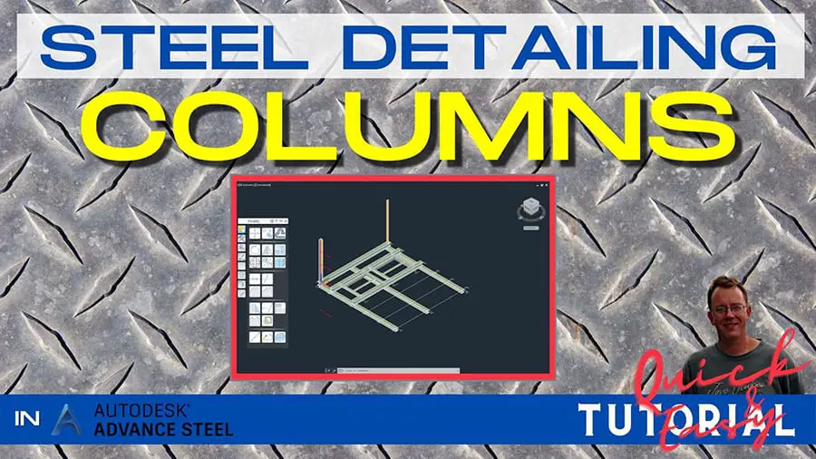
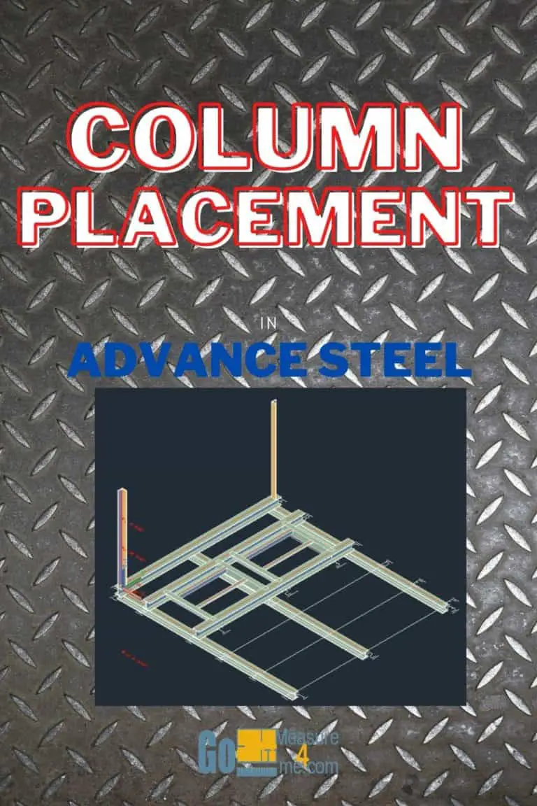
If you want to start working in Advance Steel and you want to learn how to detail steel for steel production, this tutorial is for you. I am sharing the entire process of making a Steel Platform used by CTA Chicago Transit Authority for maintenance. I will show you the entire procedure from setting up a new project to making a final set of drawings, and also how to make revisions to your project. In this article, I will show you how to create columns in Advance Steel.
This is not a standard Advance Steel project, but that is why I have decided to share it with you. Once you get an idea of how to detail this platform, making any other project will appear very easy.
Click on the video below to watch a step-by-step tutorial on how to create columns in Autodesk Advance Steel:
Open Advance Steel
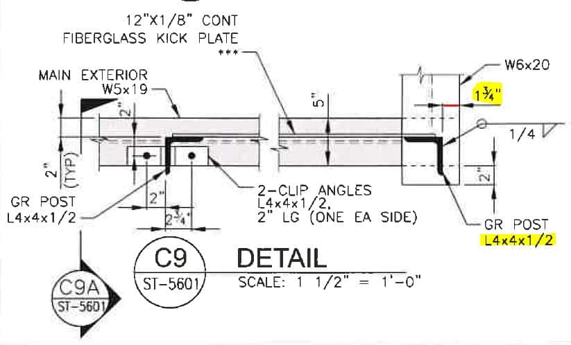
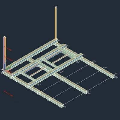
We will be creating the columns sitting on the top of W6x20 beams as shown in the detailed drawings below:
Open a Project File – you can find a free download link here.
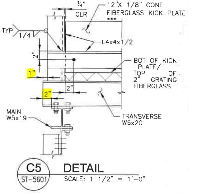
We will be placing an L4x4x1/2” post on the top of W6x20 beams. These are going to be corner posts for the railing. As you can see, the post is 1 3/4” from the edge. And in the other direction, it is 1” from the edge of W6x20 as shown here on the section view.
Go to the Top View. First, I need to extend the W6x20 beam to pass a W5x19 beam by 2”. I will do the same on the other side of this platform to match the section view I just showed you.
Change the view type to 2D Wireframe. I am also going to extend the beams below to align with the edge of the beam on top.
So, we are done with all the prep work. Let’s place our columns!
Column Placement On Grids And Proper Levels
Go to Workplanes in Project Explorer. As you can see, we need to place the bottom of our column on the top of the beam that corresponds to the level 6 3/16” above Level 0, which is Level 1 in our case.
Click to choose the bottom level of the Level 1 column. And, at the top of the column, pick Level 4. Our new column will be placed between those two levels.
Pick a Column Tool in the Home Tab – Object Section. Click where the two grids intersect. We just placed our first column. Go to the other side of the platform and click the grid intersection again. Click ENTER.
In the dialog box, we need to choose the proper column type. We need to choose L4x4x1/2”.
First, let’s select the section where we need an angle. Then confirm that we need AISC Identical Angles and, in the last dropdown, let’s find our L4x4.
Now, let’s adjust the positioning of the column. Double click on our angle. Go to Positioning. Let’s rotate this angle into a proper position. Close the dialog box.
Now move the angle to align with the edge of the beam. The other side of the angle needs to go passed the edge of the beam by 1”. First, I have aligned with the angle of the beam, and then I have to move it by 1”.
As you might remember, the beam is offset by 1 3/4” from the other edge of the beam, so let’s move it. Our first column is adjusted properly.
Now, let’s do a similar thing with the column on the other side of our platform.
Double-click the column. Go to Positioning. Rotate the column. Align it with the beam’s edges. Move to the proper distances from the edges.
Go to the 3D View. Change the Visual Type to Conceptual.
The columns are in place, with proper heights, and in the proper position.
All My Course Content
Here is my entire course topic content by topic:
08 Adding Bolts To Custom Clip Angle Connection
12 Numbering Pieces And Assemblies
13 Creating Erection Drawings
14 Creating Shop Drawings
15 Making Revisions
16 Final Thoughts
My Toolbox
If you interested in seeing what I use for my daily work, check out My Toolbox post here.