If you want to start working in Advance Steel, if you want to learn how to detail steel for steel production – this is tutorial for you. I am sharing entire process of making a Steel Platform used by CTA Chicago Transit Authority for maintenance. I will show you entire procedure from setting up a new project to making a final set of drawings and then also how to make revisions to your project. In this article I will show you how to create beams in Advanced Steel.
This is not a standard Advance Steel project, but because of that I have decided to share it with you. Once you get the idea how to detail this Platform – making any other project will appear very easy.
Save this Pin to your Pinterest Advance Steel board:

Click on the video below to see step by step tutorial how to create beams in Autodesk Advance Steel:
Here is the completed Levels Project File for you to download for free.
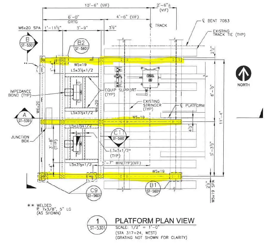
Placement Of W6x20 On Upper Level
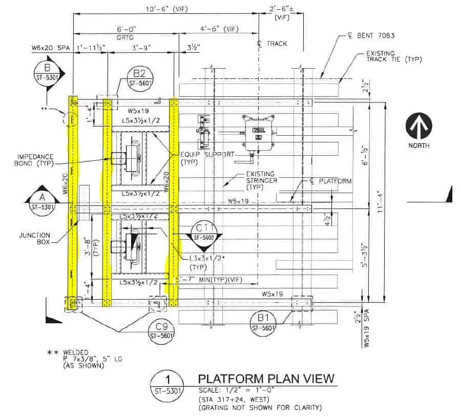
We are going to create three W6x20 beams first.
I made Level 1 active. Level 1 is exactly the beam height distance of 6 3/16” from Level 0. Choose a Rolled I Section.
Now I click on the point where Grid 1 and Grid A intersect. Then I need to click where the beam ends on the intersection of Grid A and Grid 3. Our first beam is in place. Now I need to specify what kind of beam it is. In the beam dialog box, I have to choose a W6x20 beam. In the Positioning, I have chosen the Top Middle point. This is where my beam will be attached to the grid.
As you can see in 3d view the beam is placed at the correct level and the bottom of this beam is aligned with the level below Level 0.
Go to the Top View again. Choose a Rolled I Section again. Place the beam on Grid B. Since it is the same beam click Enter to accept the settings.
Choose a Rolled I Section again. Place the beam on the Grid C. Close the dialog box to accept the settings.
Placement Of W5x19 On Lower Level
Now let’s place W5x19 beams on the level below – Level 0. Choose Level 0 in the Model Views. Run a new beam on Grid 1 from Grid A to Grid F. Choose W5x19 from the list and close a dialog box. Now as you can see in the 3d View beam is placed below the beams W6x20.
Place the beams on Grids 2 and Grid 3.
In 3d View, when you activate a level above you can see our structure of the beams completed.
Placement Of Additional Angles On Upper Level
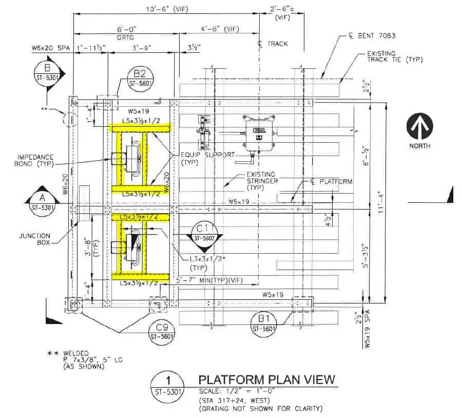
Now is time to place remaining angles: L5x3 1/2x ½” on Level 1 – tops aligned with W6x20 beam.
Choose Level 1 in Model Views. Choose Rolled Section again. Place it on corresponding grids.
Choose in the dialog box Angle, then Not Identical, and then L5x3 1/2x ½”. Close dialog box.
As you can see in 3d view, the positioning of the angles needs to be adjusted so the angles are not upside down.
Double click on an angle. Go to Positioning. Adjust the Offset and Angle. The second angle is mirrored. I changed the offset on Z-axis by 1 5/8” of an inch.
Do the same for the remaining 2 angles.
Let’s place the remaining four angles, with tops aligned to W6x20. Make Level 1 active.
Place a Rolled I Section again. Place a structural member. Choose Angle Identical in the dialog box. Choose L3x3x ½”. Adjust the positioning of an angle. Let’s move the angle to the approximate location. Now copy this angle. Let’s mirror this angle.
Select both angles and copy them to another side.
All the beams are placed successfully.
The Entire Course Content:
Here is the entire course topic content by topic:
08 Adding Bolts To Custom Clip Angle Connection
12 Numbering Pieces And Assemblies
13 Creating Erection Drawings
14 Creating Shop Drawings
15 Making Revisions
16 Final Thoughts
My Toolbox
If you interested to see what am I using doing my daily work, check out My Toolbox post here.