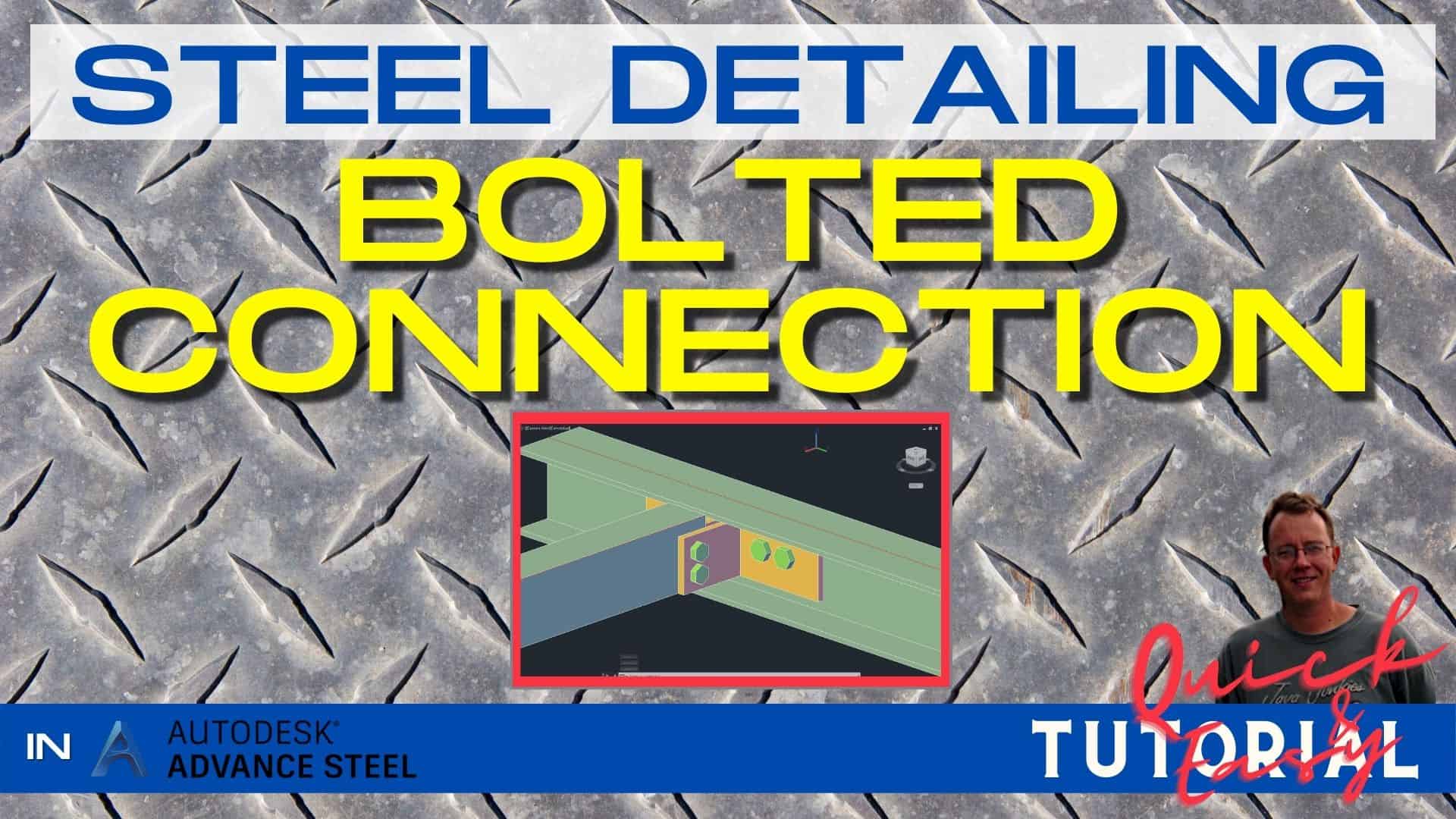
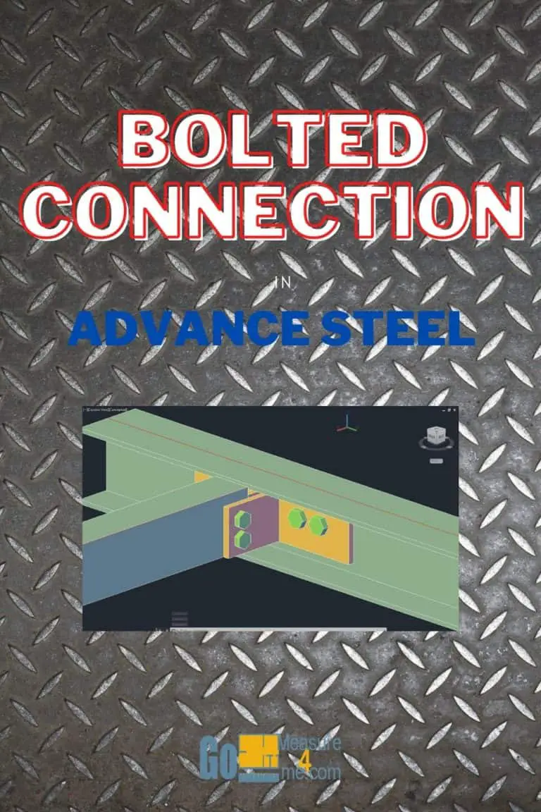
If you want to start working in Advance Steel and you want to learn how to detail steel for steel production, this tutorial is for you. I am sharing the entire process of making a Steel Platform used by CTA Chicago Transit Authority for maintenance. I will show you the entire procedure from setting up a new project to making a final set of drawings, and also how to make revisions to your project. In this article, I will show you how to add bolts to a custom clip angle connection in Advance Steel.
This is not a standard Advance Steel project, but that is why I have decided to share it with you. Once you get an idea of how to detail this platform, making any other project will appear very easy.
Download And Open a Project File
Download, Unzip and Open a Project File – you can find a free download link here.
Adding Bolts - Description of the Connection
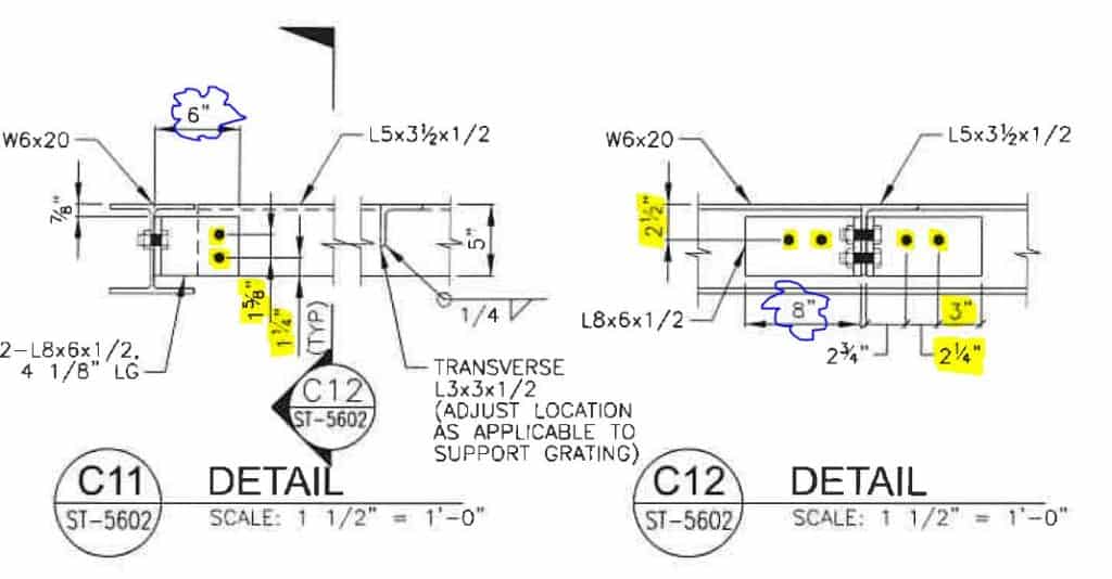
We are going to make a custom bolted connection for the Double Clip Angle as shown in this drawing. Please note that I’ve highlighted in yellow all the important dimensions. On the 6-inch side of an angle, we are going to place two vertically placed bolts – 1 1/4 inch from the edge, with spacing 1 3/8 of an inch between the bolts. On the 8-inch side, we are going to place two bolts 2 1/2 of an inch from the top of the W6x20 beam and 3 inches from the edge and 2 1/4 of an inch spacing between the bolts. There is no option in Advance Steel to place bolts in the standard clip angle connection, so this is a workaround for this problem.
Complete Video Instructions
Click on the video below to watch a step-by-step tutorial on how to add bolts to a custom clip angle connection in Autodesk Advance Steel:
Preparation Of The View
Zoom in on the clip angle connection you want to modify and select the object you want to be a part of the connection. Then, change the Visual Style to the 3D Wireframe. Then open an Advanced Steel Tool Palette. We need to set a UCS on the face of the angle. The angle will be our X- and Y-axis, and the bolt will be placed on the Z-axis. Click on the top UCS middle icon with the number 3. Now, place the first point of the axis in the corner of an angle. The second and third points snap to the outside and inside corners of this angle. Very important – you need to pay attention and snap exactly at the corner points; otherwise the workplane will be skewed.
Drawing Temporary Lines
Now, it is time to draw some temporary lines to define where you want to place the bolts. Draw 1 1/4″ line from the bottom edge of the angle. Since the other angle is on a different workplane, you cannot snap my line to this angle. The workaround is to trim to this line. I finished my line a little past this line. Now, I need to copy this line 1 3/8″ from my first line. I am deleting the first line since I’m not going to need it. Use the TR trim command to trim the ends of our temporary lines. Select those lines, click G for the group, and click Enter.
Set UCS to Global, and let’s take a look at how it looks in 3D View. Our lines are aligned correctly on the workplane we set earlier.
Inserting Bolt Pattern
Go to the Objects tab and to Switch Bolt Type and choose Bolts. Select Rectangular 2 Points. Now, select all three objects we are going to connect. Click Enter. Be sure to set the workplane to be on the face of the angle; otherwise, the program will place the bolts facing the wrong direction. Now, the workplane is set. Click Rectangular 2 Points. Select all three elements to connect. Click Enter. Define the rectangular on the temporary lines we drew previously.
A dialog box will open. Now, check if all the parameters of the bolts are as you wish them to be. The structural engineer specified 7/8-inch bolts for this connection. Now, the distance – enter the bolt quantity in the vertical and horizontal planes. I have bolts in X-axis set to 1 and in the Y-axis set to 2. Also, the spacing between the bolts is 1 5/8″. Everything looks fine. Close the dialog box.
Changing Bolt Size
When you go to Front View of our connection, which in our case is Top View since we modified UCS, you will notice that the bolts specified by the structural engineer are too large. Let’s make those bolts a bit smaller so you can actually tighten them in the field.
Change the Viewport type to be Conceptual. Now, when you click on the 3D view, you can clearly see that our connection is just perfect. All the holes are drilled.
Double-click on the bolts and change the size to 3/4″. Close the dialog box.
Right-click on your mouse. Choose the End Object Isolation option. Now, let’s take care of the other side of the angle with horizontally positioned bolts.
Adding Bolts On The Other Side Of An Angle
Choose both angles and beam. Choose the Isolate Object option. Place UCS at the corner of this angle to set up a face of this angle as our workplane. Change the View Type to 3D Wireframe.
As you can see, we have to place our bolts 2 1/2″ from the top of the beam. Since the beam is on a different workplane than our angles, we have to trim the temporary line again. Draw the line going up. Type TR for trim command. Click on the part of the line you want to remove.
Press L to draw a line. Now, draw the line with the beginning insertion point of the temporary line we just drew. Type 2 1/2 and click Enter. Now go to the left and type 3 since our bolt pattern should be three inches from the edge. Then go 1 inch down and 2 1/4 to the left to specify a temporary line for our second bolt in this pattern. Delete all the temporary lines we are not going to use. Now, in between the angles, draw a line – we need to make a temporary line to mirror our pattern onto the second angle. Now, draw the line starting in the center of the short line. Delete the short line; we not going to need it.
Select the group with the lines. Type MI for mirror. Mirror the group on the centerline we just drew. Delete the mirror line. Select both groups and group them. We can use this group to create a bolted connection on the other clip angle connections we have in our project.
As you can see, in 3D view, our lines are drawn on the wrong face of the angle. Let’s correct this issue. Change the view type to Wireframe again. Let’s check on which plane those lines are drawn by drawing a line and trim it. It is drawn on the back face of the angle. Move the groups to the front using the angle thickness as a guide.
Draw 1-inch lines since we need to draw a rectangular pattern for our bolts. Select all temporary lines and hit G for Group. Go to move tool and move all the lines by angle thickness.
Now, when you change the Viewport Style to Conceptual, you can clearly see that our lines are drawn on the face of the angles. Change the style to 3D Wireframe again.
Choose the Bolt Rectangular option on the Ribbon. Choose an angle and the beam. Click Enter. Now draw a rectangle to place our bolts on the temporary lines we drew. Check the bolt type and invert them. They should be facing the other direction. I like to keep things organized. Close the dialog box.
Repeat the procedure on the other side. Choose the beam and the other angle. Draw the rectangular for the bolt pattern. Double-check the bolt parameters. Close the dialog box.
Change the view type to Conceptual. Right-click and choose the option End Object Isolation. Our clip angle connection looks very good. Now, you can copy all the temporary lines we drew for our connection onto other clip angle connections and make those bolted connections for other members. Do not just copy bolts. I know, theoretically, it makes sense, but disaster will happen – you will copy not only the bolts but also the beams to which all the bolts are connected. I know it makes no sense at all – but this is how Advance will execute your request. You will have a countless number of beams, and cleaning this mess up later would be very difficult.
All My Course Content
Here is my entire course topic content by topic:
08 Adding Bolts To Custom Clip Angle Connection
12 Numbering Pieces And Assemblies
13 Creating Erection Drawings
14 Creating Shop Drawings
15 Making Revisions
16 Final Thoughts
My Toolbox
If you interested in seeing what I use for my daily work, check out My Toolbox post here.