To make a welded connection in Advance Steel, click Weld Point on the Home tab (Objects section), select the two parts to weld, press Enter and click where the weld symbol should go. Then set the weld type (for example Fillet Weld), the size and whether it’s continuous in the weld dialog. The weld shows up on the shop drawings with the right symbol.
This is Part 05 of my Advance Steel tutorial series for beginners, on the CTA maintenance platform. The corner posts from the last part are just floating on top of the beams right now. In this part we weld them down. It’s a short one, but welds are where a lot of shop questions come from, so it pays to model them clearly.
Video version:

What weld does the detail call for?
Download the project file free here and open it.
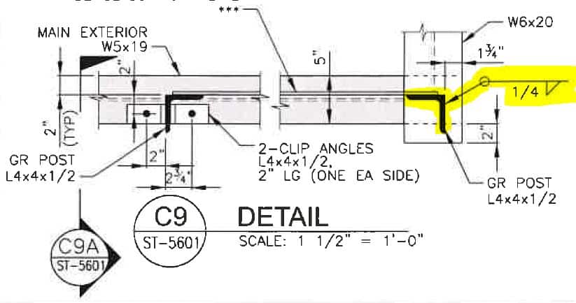
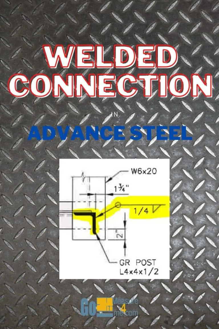
The structural engineer asked for the L4x4 post to be welded to the W6x20 beam with a continuous 1/4″ shop weld. That’s what we’ll model.
How do I weld two parts in Advance Steel?
- Zoom in on the post. Switch the visual style to Wireframe. Welds are much easier to place when you can see through the parts.
- On the Home tab, in the Objects section, click the Weld Point icon.
- Select the two parts to weld and press Enter.
- Click where you want the weld symbol to go.
- In the weld dialog, leave the type as Fillet Weld and the size at 1/4″, and check Continuous so the weld goes all around the angle.
- Close the dialog.
Do the same for the post at the other end of the platform.
That’s it. The posts are welded to the beam, and the weld will show up on the shop drawings with the right symbol, so the shop doesn’t have to call and ask. If you want to go deeper into weld types and symbols, see All about welds and weld symbols in Advance Steel.
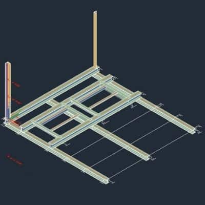
Why does the weld matter for assemblies?
A weld point isn’t just a symbol. It tells Advance Steel that the parts belong together. Parts connected by shop welds become one assembly, with one main part, and that assembly gets its own assembly drawing and mark. If you forget the weld, the post and the beam come out as separate pieces on the drawings. That’s covered in numbering the structural model.
Shop weld or field weld?
The weld dialog lets you say whether a weld is made in the shop or in the field. That changes the symbol (a field weld gets the flag) and how the parts are grouped. Model it the way the engineer’s detail says. Here it’s a shop weld.
Weld sizes and types are design decisions. Take them from the engineer’s details and ask the engineer if anything isn’t clear.
What to do when the weld doesn’t show up
- No symbol on the drawing. Check the drawing style shows welds, and that the weld point is actually connected to both parts.
- The parts aren’t in one assembly. You may have selected only one part, or the weld is set to field. Re-create it with both parts selected.
- The symbol is in an odd spot. Move the weld point to where the weld is. The symbol on the drawing points to it.
Next: 06: Shorten beams.
The whole mini tutorial series
- 00: Set up the project information
- 01: Create the grid
- 02: Create levels
- 03: Place beams
- 04: Create columns
- 05: Welded connections
- 06: Shorten beams
- 07: Custom clip angle connection
- 08: Adding bolts to the clip angle connection
- 09: Adding T-braces
- 10: Slanted beams
- 11: Clipping the beams
If you’d like to see the hardware and software I use every day, it’s all on my toolbox page.