If you want to start working in Advance Steel and you want to learn how to detail steel for steel production, this tutorial is for you. I am sharing the entire process of making a Steel Platform used by CTA Chicago Transit Authority for maintenance. I will show you the entire procedure from setting up a new project to making a final set of drawings, and also how to make revisions to your project. In this article, I will show you how to add custom T-Braces in Advance Steel.
This is not a standard Advance Steel project, but that is why I have decided to share it with you. Once you get an idea of how to detail this platform, making any other project will appear very easy.
Download And Open a Project File
Download, Unzip and Open a Project File – you can find a free download link here.
T-Bracing Requirements
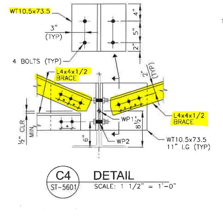
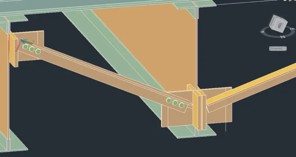
Just four inches above the bottom of the platform, we will add two T-Braces as shown below:
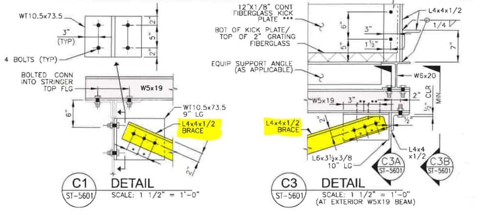
And on the upper level, we will add T-Brace and an Angle Brace as shown here:
Complete Video Instructions
Click on the video below to watch a step-by-step tutorial on how to add T-Braces in Autodesk Advance Steel:
Preparation Of The View
Download the free project file. The link to this free project file is provided in the description. Once you’ve downloaded the project file, open it.
First, we will create some levels for our T-Braces. We will make T-Braces as columns, so we need to attach the bottom and top of each T-Brace to specific levels (If you want to learn more about creating levels in Advance Steel, check out my tutorial on creating levels).
Create Top And Bottom Levels For Lower Braces
Create a level below Level 0 four inches from the bottom of the platform. I’m calling this level “Level A-Plate”. As you can see on the design drawing, the height of the brace should be two inches plus five inches plus four inches – a total of 11 inches.
I have created a temporary line with the start point four inches above the level of the bottom of the platform. The line has a length of 11″ exactly the height of the T-Brace. I drew this line to avoid making calculations and possible errors.
When you click on the line, you can discover in the properties panel the correct measurement values for the bottom and the top of this brace. In our case, that is minus 3′ –7 3/16″ and minus 2′ –8 3/16″.
I know my exact values for the top and bottom of my brace, so let’s modify the level we have created earlier. I double-click on the level I want to modify, and the dialog box opens. Now, I type in the correct measurement values for the bottom of the brace. I also check the base level as Level 0. Then I click OK to close the dialog box.
You can clearly see now that the level was moved to the bottom of the temporary line I drew a moment ago. Now, let’s create a level for the top of this brace.
Click on “Create Level” and check the option “Add level below the building”. First, rename the level. Then, change the altitude of the level. Change the “Top-level” to <none> and click OK.
Your new level has been created. Go to properties of this level and change “Base level” to Level 0. Click OK.
Now you can clearly see that the new level was added at the top of the temporary line. Now, since we don’t need this line, you can delete it from the project.
Create First T-Brace
Now, it’s time to place our first T-Brace. Go to “Workplanes”. Set the top and the bottom of the column. Use the levels we just created. Go to “Top View” and change the view to “2D wireframe”. Go to the “Home” tab and click “Create Column” in the “Objects” section.
Place the new column. I am placing the column on the edge of the existing vertical plate so I can move it more easily in the future. It acts as a reference point, and it does not crowd the place under the beam where it is supposed to be. I can move it easily once everything is set.
Now, once you’ve placed the column, a dialog box will open. Choose “T-Sections” from the drop-down menu, and then “WT (Imperial)”. Now find WT10x73.5 and choose it as your profile.
Go to positioning. Choose top and center points as your alignment point. Choose the rotation “90 degrees”. Close the dialog box.
Change the “View Type” to “Conceptual” and click on the 3D view. As you can see, the T-Brace is placed. The only thing is – I need to adjust the position of the brace (so it is aligned with the face of the plate) by moving it to the right. As you can see, the gap between the plate and the T-Brace is gone.
Mirror T-Brace
Now, I want to place a copy of the T-Brace on the other side of the steel plate. In order to do this, first I need to lock the UCS to the current elevation view (or any 2D plane). Then I go to “Modify” and simply mirror the brace with the center of the center of the steel plate.
Now, I have the first two braces placed.
Create Upper T-Brace - Levels
Now, it is time to place the brace four inches just below the top of the stringer on the left. In order to do that, I need to create two additional levels for the top and for the bottom of this brace.
As you can see on the design drawing, the upper brace is two inches plus five inches plus two inches tall for a total of nine inches.
Click on “create a new level”. Rename it. I named mine “Level – C – Plate”. I changed the altitude of that level to -13 inches. Then I specified the “Top Level” as <None>. Close the dialog box by hitting OK.
Find this level in “Model Views”. Click to edit the properties of this level. Change the “Base Level” to Level 0. Click OK to close the dialog box. Click “create new level”. In the dialog box, specify the name for the new level. I called mine “D-Plate”. Then I specified an altitude of -4 inches. Then click OK.
Find this level on the list and click “edit properties”. Change the base level to Level 0. Click OK to close the dialog box.
Create Upper T-Brace
Now, let’s place the last brace in the left top corner of the platform. Go to “Workplanes”.
Choose a level for the top of a column, and a level for the bottom of the column. Go to Home -> Objects -> Create Column and place a column on the corner of the plate.
Go to “Positioning” and adjust the positioning of this WT brace. In 3D view, you can confirm that your new brace is placed properly.
Add An Angle Brace
The last thing left to do is – the placement of the angle on the far end of the beam. In order to do that, I’m going to draw two temporary lines to find a proper place to make the angle.
Use the TR Trim command to get rid of the unwanted lines.
Select the lines and group them using “G – Group command”. As you can see on the design drawing, we need to place 6 x 3 1/2 x 3/8 angle, which is then inches long. The angle should be separated 1/2 inch from the 4×4 angle.
We are going to draw our angle on Level -1. Go to Workplanes. For the top and bottom, choose Level -1. Choose Rolled I-Section from the Menu in the Home/Objects tab. Pick an end point of the temporary line we created earlier.
Start drawing a beam. Since we are in 3D view, I want to make sure that the beam will follow the direction of the line, so I just point to an endpoint of this line and type in a value of 10. Click Enter.
Your beam is created; let’s change its type. Double-click on the beam. Choose “Angle”. Choose “Not Identical”. Choose L6x3 1/2×3/8. Go to “Positioning”. Choose “Offset” in the angle corner. For the rotation, choose “180” and “Mirrored”. Close the dialog box.
Now, you might remember that we need to move our angle 1/2 of an inch from the angle L4x4 running perpendicularly to our 6×3 1/2 angle.
Select the angle. As you can see, our angle is not aligned perfectly to the temporary line. If you try to move it, it won’t work since it is glued to the level. The way around it is to just copy it. Copy the angle and delete the original.
Choose the “Move” tool from the “Modify Palette” option. Grab the corner of the angle and move it by snapping to the endpoint of this angle and typing “4 1/2“.
One more thing: Let’s align the faces of the angle and T-Brace. Select the angle and temporary lines. Select the “Move” tool from the palette. Move them to the face of the T profile.
We have prepared all the T-Braces brackets for the Angle Braces. We will insert the angular bracing in the next tutorial. Please check it out.
All My Course Content
Here is my entire course topic content by topic:
08 Adding Bolts To Custom Clip Angle Connection
12 Numbering Pieces And Assemblies
13 Creating Erection Drawings
14 Creating Shop Drawings
15 Making Revisions
16 Final Thoughts
My Toolbox
If you interested in seeing what I use for my daily work, check out My Toolbox post here.