If you want to start working in Advance Steel and you want to learn how to detail steel for steel production, this tutorial is for you. I am sharing the entire process of making a Steel Platform used by CTA Chicago Transit Authority for maintenance. I will show you the entire procedure from setting up a new project to making a final set of drawings, and also how to make revisions to your project. In this article, I will show you how to add a custom clip angle connection in Advance Steel.
This is not a standard Advance Steel project, but that is why I have decided to share it with you. Once you get an idea of how to detail this platform, making any other project will appear very easy.
Click on the video below to watch a step-by-step tutorial on how to add a custom clip angle connection in Autodesk Advance Steel:
Open a Project File
Open a Project File – you can find a free download link here.
Unzip and Open the Project File. The link to the free file is in the description below. Go to the Top View and zoom in on the beam you want to shorten.
Adding Angles Into The Project
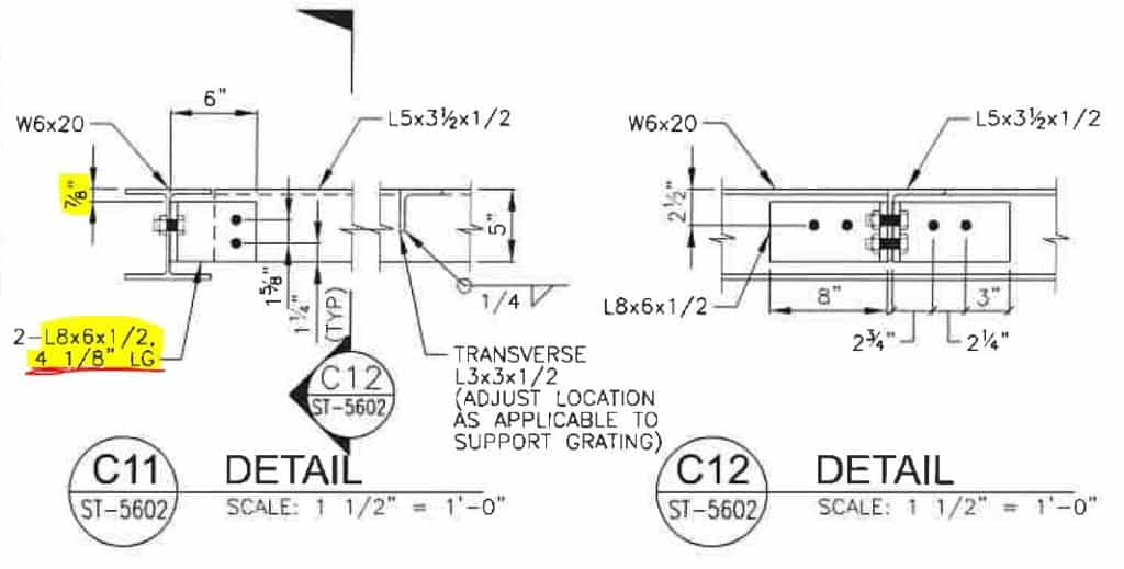
We are going to create a custom Clip Angle Connection as shown in the detailed drawing from the structural engineer. We will use an L8x6 angle. Because the bolt pattern on one side is two vertical bolts, and on the other side, it is two horizontal bolts, we need to make a custom connection. The “standard clip connection” option is unavailable.
I have already created two levels where the new angles will attach. I called them Level A and Level B. Go to Workplanes and specify at the bottom of the angle for it to attach to Level A and the top of the column to Lebel B.
Now go to Top View. Select Make Column icon on the Ribbon and click anywhere in the drawing field. We will be adjusting the position of this angle, so you don’t want to be anywhere close to existing elements to avoid Advance Steel automatically connecting to existing members.
Now, in the dialog box, choose the proper section. First, choose Angle, then Not Identical, and then look for L8 x 6 x 1/2″.
Not go to the Positioning section. Let’s set an offset in the corner. Now, let’s rotate this angle into a position. Once you are done, close the dialog box.
Adjusting Position Of Clip Angles In The Project
Now, let’s adjust the position of our angle. Let’s align this with the web.
First, let’s lock our UCS to the View. Then go to Modify and click on the Move icon and select our angle. By dragging a corner of an angle, you will align it with the horizontal angle and then move it to the web of the beam.
Now mirror this angle and move it to align with the other side of the horizontal angle.
Select both angles we just created. Mirror them by using the midpoint of the horizontal angle to the other end of this angle. Our horizontal angle has its double clip angle connection in place.
Select all four angles we just created and mirror them to the other horizontal angles in this assembly.
Now, select all eight clip angle members and copy them to the other assembly.
You can see in 3D View that all clip angles were created and placed in their correct spots.
The only thing left is – we need to create the correct bolted connections for all our custom clip angles. Check out the Bolted Connections Tutorial to see how it is done.
All My Course Content
Here is my entire course topic content by topic:
08 Adding Bolts To Custom Clip Angle Connection
12 Numbering Pieces And Assemblies
13 Creating Erection Drawings
14 Creating Shop Drawings
15 Making Revisions
16 Final Thoughts
My Toolbox
If you interested in seeing what I use for my daily work, check out My Toolbox post here.