
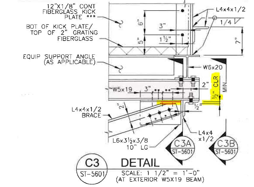
In the last tutorial, we placed slanted beams into our project. The structural engineer, however, placed a request in the design drawing that the slanted beams be separated from other structural elements by half an inch. The designer suggested that the slanted beams should be clipped (or notched) as shown in the drawing shown on the screen and marked in red. In this tutorial, we will make the designer’s dream come true – we will clip the beam!
Save this Pin to your Advance Steel board on Pinterest:

The Designer's Ultimate Desire
The detailed drawing from the Structural Platform Designer, with the 1/2″ clearance and notch marked in red:
Complete Video Instructions
Click on the video below to watch a step-by-step tutorial on how to clip a beam in Autodesk Advance Steel:
Project File Download Link
If you don’t have the file from the previous tutorial, you can download it for free here.
Preparation Of The View - Time For Total Isolation
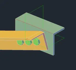
By now, our model is quite busy, so I’m going to isolate the elements on which I am going to perform the notching procedure. Select the elements, right-click to display the menu and choose the Isolate Objects option. The only elements left are slanted beams and mounting members.
Ungroup The Structural Members
The slanted angle is grouped with the other angle. Right-click on the group and find an option to ungroup it. We need those objects to be separate entities in order to perform a clipping operation on them.
Lock The UCS (User Coordinate System)
The next thing to do is mark a reference line to visually inspect that we are clipping just the right amount of the slanted piece of steel. We could measure all the required data, but for this project, visual inspection will do just fine.
We will lock our UCS on the vertical face of the mounting angle. Open the Advance Steel Tool Palette from the ribbon and find the UCS by 3 points. Then specify the 3 points on the vertical face of the angle. The X- and Y-axis will be locked on the vertical face and that is exactly what we need.
Place The Temporary Guide
Now draw the temporary line half of an inch from the top of the angle. Type L for LINE and draw the line between the two opposite corners of the angle and then move it down by half an inch. When moving, I am locking the direction of the move command in the 3D space by locking the cursor on the corner point.
Initiate Surgical Knife For Steel: Cope Skewed
Now, in the Advance Steel Tool Palette in the Features tab, find the Cope Skewed icon and select this icon. That will initiate the tool we need to make modifications to our sloped angle end.
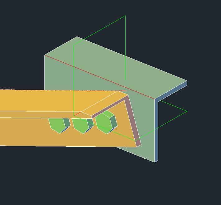
Click on the angle at the end you need to modify. The dialog box will open. Now, by entering the values in the dialog box, adjust the depth and angle of the clipping. Here I’m aligning the clipping with the white line we drew earlier. Looks like the values of 7/8 of an inch and 18.7 degrees work perfectly.
As you can see, our clipping procedure went perfectly. Now, you can put the UCS in default mode, delete the temporary reference line, and finish the object in isolation mode.
If you liked this tutorial and you wish to be notified of my future blog posts, please subscribe on the right. More tutorials are on the way!
Have a wonderful day!
All My Course Content
Here is my entire course topic content by topic:
08 Adding Bolts To Custom Clip Angle Connection
12 Numbering Pieces And Assemblies
13 Creating Erection Drawings
14 Creating Shop Drawings
15 Making Revisions
16 Final Thoughts
My Toolbox
If you interested in seeing what I use for my daily work, check out My Toolbox post here.