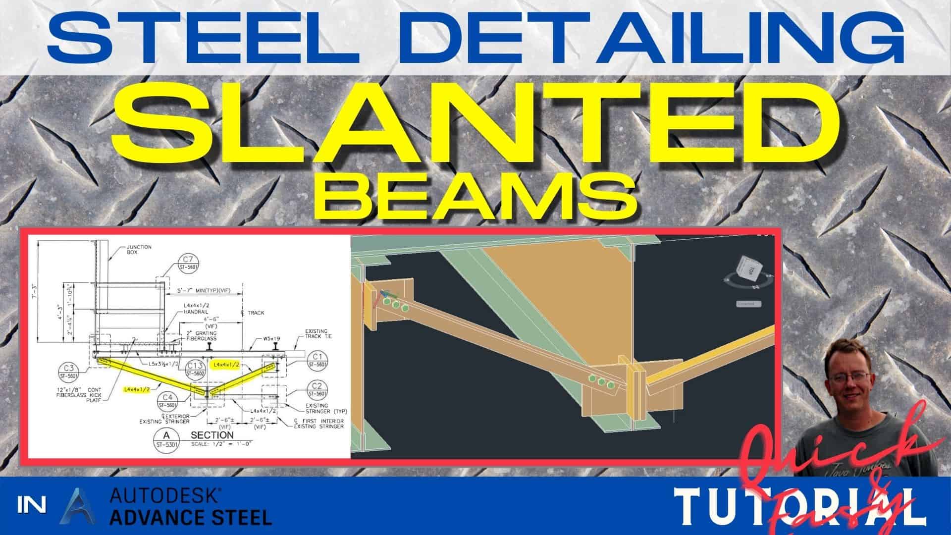
In the last tutorial we were adding a bolted connection to our project. In this tutorial, we will be adding slanted beams to our project connecting to T-Braces that we already placed in this tutorial.
Table of Contents:
Complete Video Instructions
Click on the video below to watch a step-by-step tutorial on how to clip a beam in Autodesk Advance Steel:
Project File Download Link
If you don’t have the file from the previous tutorial, you can download it for free here.
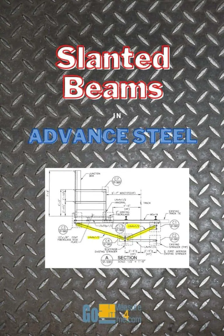
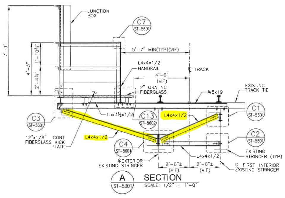
Design of the Platform with Slanted Beams
Here is the section view what we will be working on:
Preparation Of The View
First, we need to lock the UCS on the vertical face of the T-Brace to draw some guides.
In the Advance Steel Tool Palette available in the Ribbon Home Tab in the UCS section, choose UCS 3 Points and select 3 points on the face of the T-Brace.
Drawing Temporary Lines
Now we need to draw a temporary line two inches from the edge of the brace. Type L and choose a Line command. Then draw the line between the two corners of the brace.
Choose the Move tool and move the line by two inches. When moving, lock your cursor on the corner of the brace and type a value of two.
Copy the drawn line by typing C and choosing the Copy command. Move the line by two inches. Type M and choose the Move command. When moving, lock your cursor on the corner of the brace and type a value of two.
Copy the drawn line by typing C and choosing the Copy command.
Move the line by two inches. Type M and choose the Move command. When copying, lock your cursor on the corner of the brace and type a value of two.
We have marked the minimum bolt distance to edge of the bracing members.
Using the same principle, I will draw some temporary lines representing the bolt locations and where the brace ends. It should end two inches from the last bolt. You should try drawing the lines, too!
I have my temporary lines drawn.
Preparation of the Levels for the Slanted Column / Beam
The next thing to do is – we need to create two levels: for the bottom and the top of the slanted beam. I am calling mine: AA and the other one BB. My Slanted Beam, which actually will be a column, will be sitting in between those two levels.
Here I’m adjusting the numerical values of the levels, so they are at the exact level I need them to be.
The heights I’m typing in into the boxes, I acquired from the temporary lines I drew. You can get the location of the lines in the 3D space when you click on it. It will be in the properties of this line.
Once levels are set, you need to go to Workplanes to fix the top and the bottom of the column to those levels.
Go to the Top View and change the view type to Wireframe.
Placing the Slanted Column / Beam
Go to the Ribbon and activate the Column tool.
Choose the required column section. This project requires use of the Identical Angle L4 x 4 x 1/2″.
I am placing the column on the bottom end of the Slanted Column. After it is in place, we will move the top end of this column to lock with the other end of the temporary lines I prepared earlier.
But first, we need to choose the section type for our beam. This project requires use of an Identical Angle L4x4x1/2 inch. As you can see, our column is now in the form of the proper angle.
Adjusting Slanted Column Position
Now, you can click on the blue point of the column and simply drag it to the top point where it needs to be. I am locking this point with the temporary lines I used earlier for the bolts distance calculation.
The only thing left is to adjust the Positioning of this angle. Double-click on it and the dialog box will open. Go to Positioning tab. For a better overview of the current situation, I changed the view to Conceptual. The angle needs to be in the mirrored position. Close the dialog box. Our first slanted beam is in place.
Placement of the Second Slanted Beam in the Project
Now, we can make another slanted beam on the other side of this platform. The procedure is similar. First, you need to lock yourself on the proper plane and then draw temporary lines to be in compliance with the requirements set in the structural drawing. The beam edge distance needs to be two inches and the distance between the bolts 2 1/4 of an inch.
Once all the temporary lines are drawn and I made notes for the required levels on which I need to place the beam, it is time to set two workplanes for this beam. I am calling those planes CC and DD.
In the Altitude boxes, I am typing the altitudes I noted just a moment ago for the height of the beams. We will glue the beam in just a moment to those workplanes.
Set the top and bottom of the column to the workplanes you just created.
Start the Column too. The Column Tool is also in the Objects tab of the ribbon. Like before, I am placing my column on the lowest point of the slanted beam. I am going to drag the highest point of the column to the opposite end point of the slanted beam.
As you can see, the top of this column is associated with the workplane. Even when you try to change the end point of the column to the end of another line, it stays on the workplane.
The second slanted beam is in place. Now, I will place the bolts to connect the slanted beams with T-Braces. In the next episode of this platform tutorial, we will be clipping those angles, as requested by the structural designer and shown on the structural drawing.
All My Course Content
Here is my entire course topic content by topic:
08 Adding Bolts To Custom Clip Angle Connection
12 Numbering Pieces And Assemblies
13 Creating Erection Drawings
14 Creating Shop Drawings
15 Making Revisions
16 Final Thoughts
My Toolbox
If you interested in seeing what I use for my daily work, check out My Toolbox post here.